Advertisement
Quick Links
OVS-6000
MANUFACTURER'S STATEMENT
Read this installation instructions carefully before use to ensure proper operation of this product.
Failure to read this operation manual may cause improper operation and may result in serious injury or death of
a person.The meanings of the symbols are as follows.
Disregard of the warning symbol can cause improper operation which may cause death
WARNING
or serious injury.
Disregard of the caution symbol can cause improper operation which may cause injury of a
CAUTION
person or damage the object.
NOTE
Special attention is required to the section of this symbol.
It is required to check the operation manual if this symbol is shown on the product.
NOTE
1. This product is a non-contact switch intended for header mount or wall mount for vehicle detection.
Do not use for any other applications.
2. When setting the sensor's detection area, make sure that there is no traffic around the installation site.
3. Before turning the power ON, check the wiring to prevent damage or malfunction of equipment connected to
the product.
4. Only use the product as specified in the operation manual provided.
5. Be sure to install and adjust the sensor in accordance with the local laws and standards of the country in which
the product is installed.
6. Before leaving the installation site make sure that the product is operating properly and instruct the building
owner/operator on proper operation of the product.
7.The product settings can only be changed by an installer or service engineer. When changed, the
changed settings and the date shall be registered in the maintenance logbook.
WARNING
Do not wash, disassemble, rebuild or repair the sensor, otherwise
it may cause electric shock or breakdown of the equipment.
Danger of electric shock
NOTE
The following conditions are not suitable for sensor installation.
-Fog or exhaust emission around the detection area
-Wet floor
-Vibrating header or mounting surface
-Moving objects, steel plate, emergency lights or illumination in the detection area or in vicinity
-Highly reflecting floor or highly reflecting objects around the detection area
SPECIFICATIONS
Model
Detection range
Detection method
Detection range (Vertical)
Detection range (Right & Left)
Detection range (right & left)
Power supply
Power consumption
Current consumption
Operation indicator
Output
Relay hold time
Operating temperature
Weight
Accessories
NOTE
The specifications herein are subject to change without prior notice due to improvements.
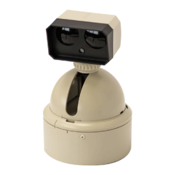
OUTER DIMENSIONS AND PART NAMES
OVS-6000
2 3/4"(70)
Mounting pitch ø85 (x3)
ø100
ENGLISH
OVS-6000
6' 6 3/4" to 19' 8 1/2" (2.0 to 6.0m)
Active infrared reflection method
-80° to +80° (Deep/Shallow)
360°
24VDC
< 2.5W (24VDC)
< 105mA (24VDC)
Stand-by
: LED ON
Detection(Only one area)
: LED OFF
Detection(Any areas)
: LED Slow Blinking
Infinite detection
: LED Fast Blinking
"Form A" relay 100VAC 1A
30VDC 0.1A Max.
Approx. 1.0sec.
-4 to 131°F (-20 to +55°C)
290g (10.2oz)
1 Operation manual
2 Mounting screws
1 Mounting template
1 Cable 9'10"(3m)
2 3/4"(70)
Without sensor head cover
OVS-6000
Operation
Presence
Sensitivity
On delay
indicator
Frequency
Indicator
① Detection window
② Sensor head
③ LED indicator
④ Sensor head lock nut
⑤ Main unit
⑥ Base lock screw
⑦ Basement
⑧ Mode setting switch
www.GateOpenerSafety.com | (800) 878-7829 | Sales@GateOpenerSafety.com
DETECTION AREA
3 15/16"
(100)
5 7/8"
(150)
7 7/8"
(200)
9 13/16"
(250)
11 13/16"
(300)
FRONT VIEW
16' 4 7/8"
9' 10 1/8"
(5m)
(3m)
NOTE
The actual detection area may become smaller depending on the ambient light, the color / material of
the object or the floor as well as the entry speed of the object.
INSTALLATION
1
Install Sensor
(1-1) Drill three mounting holes.
Affix the mounting template put "up side"
sign up and make holes. Drill a wiring hole
when you pass the cable into the wall.
・Mounting screw holes : ø1/8"(3.3mm)
(Three positions)
・Wiring hole : ø19/32"(15mm)
(One in center)
(1-2) Put attached screws into mounting holes temporary.
(1-3) Break off basement from sensor unit.
(1-4) Set basement onto temporary screws of (1-2)
(1-5) Wiring onto basement (refer to 3-1)
[inch(mm)]
(1-6) Set sensor unit on basement.
Sensor adjust
joint mark
Fixed position
Mounting basement
adjust joint mark
1'4 9/16"
(420)
2' 13/16"
(630)
2' 9 1/16"
(840)
3' 5 5/16"
(1050)
4' 1 5/8"
(1260)
SIDE VIEW
6' 6 3/4"
(2m)
9' 10 1/8"
(3m)
13' 1 1/2"
(4m)
16' 4 7/8"
(5m)
19' 8 1/2"
(6m)
: Actual detection area
: Actual detection area
3' 9/32"
0
3' 9/32"
9' 10 1/8"
16' 4 7/8"
(1m)
(1m)
(3m)
(5m)
CAUTION : Risk of product failure.
Do not install sensors upside down.
Otherwise rain water makestroubles.
Right position of the
mounting screw holes when
install on the side pole.
Mounting screw holes
Wiring holes
Right sensor position
whenuse a angle.
WARNING : Danger of electric shock.
Make sure to remove burr in mounting holes otherwise
damaged cable may cause electric shock.
Sensor
1, Loose the lock screw of basement full well.
2, Basement can break off when rotate anticlockwise.
Basement
Lock screw
Wiring should be allowed sign of basement.
① Power supply ••• Red
② GND ••• Black
③ Signal ••• White
1, Push sensor unit onto basement adjust joint mark.
Sensor
2, Rotate sensor clockwise to prescribed position.
Basement
3, Tight up the lock screw.
Lock screw
6' 6 3/4"(2m)
9' 10 1/8"(3m)
13' 1 1/2"(4m)
16' 4 7/8"(5m)
19' 8 1/2"(6m)
[feet, inch(mm)]
6' 6 3/4"
(2m)
9' 10 1/8"
(3m)
13' 1 1/2"
(4m)
16' 4 7/8"
(5m)
19' 8 1/2"
(6m)
16' 4 7/8"
9' 10 1/8"
3' 9/32"
0
3' 9/32"
(5m)
(3m)
(1m)
(1m)
Advertisement

Related Manuals for Optex OVS-6000


Summary of Contents for Optex OVS-6000
- Page 1 ENGLISH OVS-6000 MANUFACTURER'S STATEMENT DETECTION AREA Read this installation instructions carefully before use to ensure proper operation of this product. Failure to read this operation manual may cause improper operation and may result in serious injury or death of a person.The meanings of the symbols are as follows.
- Page 2 NOTE Sensor cable sensor to sensor : Please use VCTF cable 0.75mm Entry into Stopped 3 sec. or OVS-6000 the area more in the area Cable length : Please use cable within 32' 9 11/16"(10m) long between sensor to sensor.
Need help?
Do you have a question about the OVS-6000 and is the answer not in the manual?
Questions and answers