Table of Contents
Advertisement
Quick Links
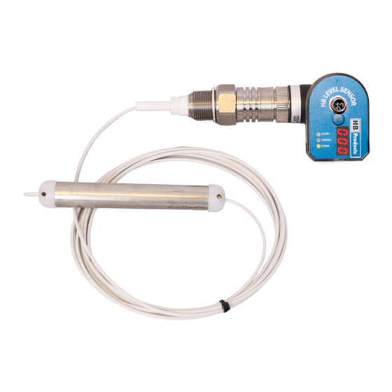
Manual for wire level sensors delivered after October 15th 2021*
Covers: HBLT & HBSLT
Wire sensor suited for liquids like NH3, and HFC/HFO refrigerants -not suited for water.
*Changes has been made to the sensor shipped from October
15th. The manufacturing date can be found on the silver label
on the electronic unit and it is the last 4 numbers in the V num-
ber in the format DDMMYY, The sensors can also be recog-
nized by the SW numbers:
73 or higher for RF3
32 or higher for RF4
The numbers are found at the top of the tool window when the
sensor is connected
Introduction
Wire and Flex are intelligent liquid level sensors which can be installed in a vessel or in a standpipe. For the Wire sensor the
sensor element is a stainless steel wire insulated with PTFE and for the Flex sensor the element is a stainless steel wire
mounted with steel tube elements to increase the sensitivity. Both sensors can to be mounted directly in a stand pipe. If they
need to be installed in a vessel they need an inner pipe. Both sensors measure between the wire/tube elements and the sur-
rounding pipe.
The sensor can be installed in refrigeration systems and similar demanding applications with high pressures and aggressive
fluids. The sensor emits a 4-20mA analog signal, which is proportional to the liquid level.
The sensors comes in different versions with or without a cable for direct valve control. All versions emits a 4-20mA analog
signal, which is proportional or disproportional to the liquid level, via the M12 plug. The sensors are available in special ver-
sions which contains a controller able to control a valve directly, without using a PLC.
Wire level sensor manual 05
ATEX/Ex versions included
October 2021 HBproducts.dk
1
Advertisement
Table of Contents

Related Manuals for HB Products HBLT


Summary of Contents for HB Products HBLT
-
Page 1: Introduction
Manual for wire level sensors delivered after October 15th 2021* Covers: HBLT & HBSLT Wire sensor suited for liquids like NH3, and HFC/HFO refrigerants -not suited for water. *Changes has been made to the sensor shipped from October 15th. The manufacturing date can be found on the silver label... -
Page 2: Table Of Contents
If changes are made to type-approved equipment, this type approval becomes void. The product's input and output, as well as its accessories, may only be connected as shown in this guide. HB Products assumes no responsibility for damages re- sulting from not adhering to the above. -
Page 3: Application Examples
Installation Instructions—wire sensor The wire sensor is designed for level measurement of liquids in vessels like, tanks, pump separators and receivers . The sensor can be mounted in a standpipe from 1” (25mm) up to 4” (100mm) diameter or directly in a vessel with an inner pipe from 1”... - Page 4 Stand pipe: DN32..…DN65. Recommended pipe standard: DIN 10220 Recommended bending: DIN 2615-1/Type 3 Recommended TEE: DIN 2615-1 Standpipe: DN65…DN100. Recommended pipe standard: DIN 10220 Recommended bending: DIN 2615-1/Type 3 Site pipe can be designed in smaller pipe e.g. o.5 x DN. Wire level sensor manual 05 October 2021 HBproducts.dk...
- Page 5 Installation Instructions—Flex sensor The Flex sensor is designed for level measurement of liquids in vessels like, tanks, pump separators and receivers . The sensor can be mounted in a standpipe 1” (25mm) or 1 ¼” (32mm) diam- eter or directly in a vessel with an inner pipe 1” (25mm) or 1 ¼”...
-
Page 6: Installation Wire
Allow for 50 mm clearance below the weight to the bottom of the tank—if relevant. To install HBLT-wire, you must use a 2.5 Separate the electronic part from the Define the required length of sensor mm Allen key, shifting spanner, and mechanical part from standpipe. -
Page 7: Installation Flex
The sensor with all elements removed from the wire. To shorten HBSLT/HBLT-Flex, you only need to remove the necessary elements. A large wire cutter is needed for the wire. -
Page 8: Connection Diagrams
• HBLC Power supply HBSLT HBSLC Connection diagram for sensors without control Suited for • HBLT and HBLT-wire & Flex cable. With and without temperature compensa- • HBLC tion +24V DC or AC - Common DO, Alarm output AO, 4-20 mA level... - Page 9 Connection diagram for sensors with control ca- Suited for • HBSLT/S and HBSLT–wire & Flex/S ble for all common stepper motor valves — here • HBSLC/S shown with Carel E2V +24V DC or AC - Common AI Remote set point 4-20 mA AO, 4-20 mA level Run in signal The sensor has a build in controller for a stepper valve.
- Page 10 Connection diagram for sensors with control ca- Suited for ble for pulse modulating valve — here shown • HBSLT/PWM and HBSLT–wire & Flex/ with Danfoss AKV/AKVA • HBSLC/PWM +24V DC or AC - Common AI Remote set point 4-20 mA AO, 4-20 mA level Run in signal The sensor has a build in controller for a pulse modulating valve.
- Page 11 Connection diagram for sensors with control ca- Suited for • HBSLT/C and HBSLT–wire & Flex/C ble for modulating valve — here shown with Sie- • HBLC/C mens MVS661 MVS661 motor valve -common - = White common + supply + = Brown Supply mA input AO = Grey , 4-20 mA mA output position...
-
Page 12: Analog Output
Connection diagram for sensors without control Suited for • HBLT and HBLT-wire & Flex cable. With and without temperature compensa- • HBLC tion Barrier +24V DC Not used Not used AO, 4-20 mA level Not used The sensor with ATEX approval use a two wire connection. -
Page 13: Use The Hb-Tool For Setting Up The Sensor
Use the HB tool for setting up the sensor The tool to be used must be version 5.5.2 or higher. You can see the soft- ware version when you open the tool and click on the About tab Setup — level or control The sensor can operate in two different modes •... - Page 14 Basic settings Filter time averages the output over a peri- Here you make the primary settings of the sensor od and reduce fluctua- tions Here you set the parame- ters for the control func- Here you set the pa- tion. rameters for the sen- When “Run in signal”...
- Page 15 Advanced settings Here you make the advanced settings of the sensor Here you set the parame- ters for the alarm func- tion. Only available for sensors without cable Here you can adjust parameters for the valve control Alarm relay function: Here, the relay function is indicated, depending upon the instructions –...
- Page 16 Diagnostic (calibration of sensor) Here you make the calibration of the sensor. If the sensor is operating in one of the predefined liquid it is delivered with a calibration and does normally not need further calibration. If you need higher accuracy the sensor can be calibrated Here you can see and change the zero Here you can see and change the SPAN calibration.
-
Page 17: Led Indication
LED indication • Green LED indicates 24 V DC supply; it flashes during operation. If "run-in" is not used, this function must be deactivated in the tool. • Yellow LED indicates control. The flashing sequence indicates if the valve is closing or opening. •... -
Page 18: Fault Detection
Please contact your local distributor about how to handle complaints. Further Information For further information, please visit our website, www.hbproducts.dk, or send an email to: support@hbproducts.dk. HB Products A/S – Bøgekildevej 21 – DK8361 Hasselager – support@hbproducts.dk – www.hbproducts.dk Wire level sensor manual 05... - Page 19 Wire level sensor manual 05 October 2021 HBproducts.dk...
- Page 20 Quick guide Installation The sensor is installed in the vessel using liquid sealant or PTFE tape like shown in the manual and the electrical unit is connected. If the electronic unit has the threaded union, make sure it is firmly tightened to secure good electrical con- nection.
Need help?
Do you have a question about the HBLT and is the answer not in the manual?
Questions and answers