Table of Contents
Advertisement
Quick Links
Installation and configuration guide
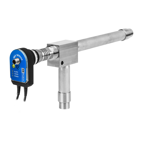
HBX Vapor Quality sensor
Sensors for optimizing Evaporator Control, both for DX (direct expansion) and
overfeed CR (Circulating Refrigerant) - systems
Angle rod version
Angle strainer version
In-line version
Introduction:
The three different versions are available, with the same function. Pipe size and piping layout, bend or
straight, is different and suited for different applications. The strainer house version has one fixed flow di-
rection, whereas the two stainless versions accept flow in both directions.
HBX Vapor Quality Sensors measures the Vapor Quality of the refrigerant vapor leaving an evaporator and
use this signal for controlling the expansion valve. Thanks to the capacitive measurement principle it is able
to measure the liquid content of the fluid leaving the evaporator without pressure drop.
For "DX" systems the vapor quality sensor can replace the conventional superheat control and is able to re-
duce the superheat to zero. The sensor can control the valve directly or it can provide the high vapor quality
measurement for an external control system. The vapor quality sensor react instantaneously if the dryness
of the gas is changed in the evaporator outlet. Experience has shown that the entire system is in better bal-
ance with minimum variation in pressure.
In overfeed and flooded systems the sensor is able to measure the low vapor quality in the evaporator outlet
and control the circulation ratio (CR) by controlling the liquid valve or the pump capacity, either directly or
as an input for a PLC.
The sensor is manufactured in stainless steel or cast steel and can be used for all commonly used refriger-
ants CO2, Hydrocarbons, ammonia, HFO's and HFC's with different settings. The HBX sensor is available in
several versions, with and without temperature sensor and cable for direct connection to an expansion
valve. Three types of expansion valves are supported: stepper motor, PWM pulse modulating ex. AKV valves
and modulating 4-20mA controlled expansion valve.
A special ATEX/IECEx (EEx ib IIC) version is available for use in special hazardous areas and with flammable
refrigerants. This product is only suited for external control and is not able to control an expansion valve di-
rectly.
HBX-all types installation and calibration manual date: 06-11-2019
WWW.HBPRODUCTS.DK
Advertisement
Table of Contents

Related Manuals for HB Products HBX Vapor Quality sensor


Summary of Contents for HB Products HBX Vapor Quality sensor
-
Page 1: Introduction
Installation and configuration guide HBX Vapor Quality sensor Sensors for optimizing Evaporator Control, both for DX (direct expansion) and overfeed CR (Circulating Refrigerant) - systems Angle rod version Angle strainer version In-line version Introduction: The three different versions are available, with the same function. Pipe size and piping layout, bend or straight, is different and suited for different applications. -
Page 2: Table Of Contents
Intended use. The purpose of the HBX sensor is refrigerant measurement and control. If the HBX is to be used in a different way, prior, written consent must be obtained from HB Products. Repair: Any repair must be carried out by a trained professional. -
Page 3: Application And Mounting Strainer House Version
Application and mounting instruction Sensor mounted in a strainer house (HBX-xxx-ST) The HBX-sensor is mounted after the evaporator and is able to measure the Vapor Quality (dryness) from 0 to 1. The output can be used as input to a PLC or it can control the expansion valve directly or both. The sensor is mounted in a strainer house where the strainer is replaced by the sensor. -
Page 4: Application And Mounting Straight Pipe Version
Application and mounting instruction Sensor mounted in a straight pipe HBX in-line The HBX-sensor is mounted after the evaporator and is able to measure the Vapor Quality (dryness) from 0.2 to 1. The output can be used as input to a PLC or it can control the expansion valve directly or both. This sensor version is mounted in a straight pipe and it accepts flow in both directions. -
Page 5: Application And Mounting Small Rod In Pipe Version
Application and mounting instruction Angle rod version The sensor accept flow in both directions, but have to be mounted in downward sloping pipes to ensure drainage of refrigerant, and oil. The sensor can be mounted in different positions. But some will be sensitive to oil contamination and trapped refrigerant during startup. -
Page 6: Installation Of Temperature Sensor
Installing the HBX-DX Sensor The sensor is installed in the outlet of the evaporator, as part of the suction line. Soldering connection, fittings and pipes are made of stainless steel. The sensor part itself must be removed by unscrewing it from the steel block/base part before sol- dering. -
Page 7: Removal Of Electrical Unit
Removal of the electrical unit The threaded union between the electronic and mechanical part allows for fast removal and remounting of the electronic element without interfering with the pressurised system. No tools are needed for the operation. End view without electronic unit Sensor configuration All HBX sensors can be calibrated using a pc and a M12 -USB cable. -
Page 8: How To Use The Sensor
How to use the sensor Two different versions Two different versions exist • A pure sensor version—without the controller capability • A version which can both control an expansion valve with a simple input and act as a sensor together with a PLC The sensors are able to control an expansion valve has a cable beside the temperature sensor cable, which can be connected directly to the valve. -
Page 9: How Does The Control Work For Dx Operation
How does the expansion valve control loop work for DX operation From stop to Start To start the process you need to activate the run in signal by applying 5-24 V on pin 5 when you remove the voltage the system will stop. - Page 10 What happens when the process is disturbed If something happens with the complete system which results in liquid in the evaporator outlet there is a build in safety system that protect the compressor. If the sensor measures a “X” value lower than the “low limit safety alarm in “X” the valve will be closed rapidly until setpoint “Degree of dryness “X”...
-
Page 11: Sensor Setup Basic Settings As Controller
How to setup the sensor as direct controller of a expansion valve. Typical values for DX operation Set the degree of dryness, ”X” value. For DX operation a good starting point would be 0.985 the closer to 1 you go the dryer the gas will be. The X value is the Vol% of liquid Set the P-band to 30% as a starting point. -
Page 12: Sensor Setup Advanced Settings As Controller
Advanced settings for sensor as direct controller of a expansion valve. Stepper motor settings only ap- pear in sensors with built-in step- per motor print. Can be used for all valve types, stepper motor settings must match manufacturer's instruc- tions. Displayed settings are for a Carel EV2 valves. -
Page 13: Sensor Setup Basic Settings For Plc Input
Using the sensor for controlling a flooded or semi flooded evaporator The sensor have to be set to flooded operation called “HBX-CR” this is normally done at delivery. If this is not done or the sensor have to be used for another purpose it can be changed in the Calibration tab in the HB tool. You start by ticking off the three small boxes to the right. - Page 14 How to setup the sensor as input for PLC Typical values for DX operation When the sensor is not operating as a controller some of the parameters are irrelevant and the boxed are inactive and shown in grey. Set filter time to 2 seconds. The filter time is the period of time over which the X measurement is evened out.
-
Page 15: Connecting Diagram Stepper Motor
Advanced settings for sensor as input for PLC Alarm output, NO (normally open) or NC (normally closed) , default is ”NC” (Fail safe function) After Changing settings push the button ”Save to sensor” (a message ”OK” on the screen indicate that the settings is saved) Save settings file is used to save all the settings as a txt file Load settings file is used to set up all parameters from a existing txt file (copy data to a new sensor) -
Page 16: Connecting Diagram Motor Valve
Connection diagram for HBX/S (stepper motor) with temperature compensation — here shown with Carel E2V +24V DC - Common AI 4-20 mA Remote settings* AO,4-24 mA level ** DI start stop Run IN signal 5 to 24 V *Please see appendix for description of remote settings ** When the sensor is very wet it will deliver 22 mA •... -
Page 17: Connecting Diagram Pulse Modulating
Connection diagram for HBX/C motor valve— here shown with Siemens MVS661 MVS661 motor valve -common - = White common + supply + = Brown Supply mA input AO = Gray , 4-20 mA mAoutput position Open/Close valve Motor valve: 4-20 mA 24 V DC, max 24 W 3 wire connection Manual open/close +24V DC... -
Page 18: Connecting Diagram Plc And Atex
Connection diagram for HBX/PWM— pulse modulating expansion valves Danfoss AKV/AKVA and Hansen PXV/PXVW Wiring using cable Wiring using M12 connector HBSSR box solid state relay Power input 24 to 240 V AC HBSSR box solid state relay Power input 24 to 240 V AC +24V DC - Common DO—PWM +24V DC... - Page 19 Connection diagram for sensor without control cable, connected to PLC +24V DC - Common Not used AO,4-24 mA level vapor quality ** Not used ** When the sensor is very wet it will deliver 22 mA Analog output The analogue 4-20 mA output on pin 4 is linear with the “Degree of dryness “X” as shown in the table. This is similar for all types of sensors in DX operation.
-
Page 20: Calibration Of Sensor
Calibration of sensor for DX operation The sensor is delivered with a basic calibration for the refrigerant you specified when ordering. The sensor can be used directly without further calibration. You can check the calibration as described below. If the calibration is not optimal the accuracy can be improved by making a simple dry calibration at normal operating temperature., when the system has been operating for some hours. - Page 21 How to check your calibration and make a new calibration while sensor is connected to PLC Start your refrigeration system and let it reach normal operating temperature. Make sure the sensor is completely dry by closing the expansion valve manually and wait for the system to evap- orate all the refrigerant Read the minimum “Actual measurement in pF”...
-
Page 22: Remote Setting
Remote setting (Only special versions of the sensor) For special versions of the sensors controlling an expansion valve or a liquid valve there is a possibility to change the “degree of dryness X” dynamically from a PLC. This is done by using a function called remote setting and it is activated by selecting “Remote setpoint”... -
Page 23: Led Indications On Sensor Head
The sensor must be ordered for used refrigerant. If used for another refrigerant/media it must be updated with new settings. HB products has the setting files for most refrigerants and you can get them on request. HBX-all types installation and calibration manual date: 06-11-2019... - Page 24 Contact HBproducts support if you need more information Email: support@hbproduct.dk Telephone : +45 8747 6200 HBX-all types installation and calibration manual date: 06-11-2019 WWW.HBPRODUCTS.DK...
Need help?
Do you have a question about the HBX Vapor Quality sensor and is the answer not in the manual?
Questions and answers