Table of Contents

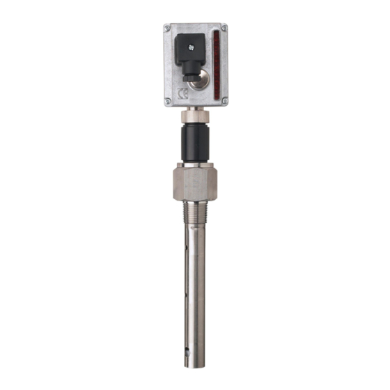
Summary of Contents for HB Products HBLT-A1
- Page 1 WE INCREASE UPTIME EFFICIENCY IN THE REFRIGERATION INDUSTRY Instruction manual HBLT-A1 LIQUID LEVEL SENSOR for measuring liquid level in refrigerant vessels Instruction manual HBLT - A1 - Liquid level Transmitter (HBLT-A1-008-UK) 1 / 16...
-
Page 2: Table Of Contents
Reset to factory setting ..............11 LED indication ................11 Practical calibration hints .............. 12 Trouble shooting................15 Further information ............... 15 Declaration of conformity (CE) ............16 Instruction manual HBLT - A1 - Liquid level Transmitter (HBLT-A1-008-UK) 2 / 16... -
Page 3: Safety Instructions
HB Products accepts no responsibility for damage as a result of a failure to observe these instructions. Conditions of guarantee and responsibility in HB Products’ sale and delivery terms are not extended because of the directions above. -
Page 4: Introduction
(4 to 20 mA) making it possible to display/control and/or regulate the liquid level when used in conjunction with a controller. NOTE! To avoid accumulation of oil in the stand pipe a 10deg. slope on connection pipe is recommended. Instruction manual HBLT - A1 - Liquid level Transmitter (HBLT-A1-008-UK) 4 / 16... -
Page 5: Technical Data
The electronic head and sensor tube can be separated by hand without emptying the vessel/standpipe. This allows installation of the sensor tube and later mounting the electronics or easy replacement if needed. Instruction manual HBLT - A1 - Liquid level Transmitter (HBLT-A1-008-UK) 5 / 16... -
Page 6: Factory Setting
When designing the stand pipe please make sure to create a slope on the connection pipe. This prevents accumulation of oil Mounting instruction To install the sensor Teflon (NPT”) tape or sealing ring(BSPP) is required. Instruction manual HBLT - A1 - Liquid level Transmitter (HBLT-A1-008-UK) 6 / 16... -
Page 7: Electrical Connection
WE INCREASE UPTIME EFFICIENCY IN THE REFRIGERATION INDUSTRY Add Teflon tape to thread for NPT”. Mount the sensor on the vessel. Torque 80-150 Nm. Electrical connection Instruction manual HBLT - A1 - Liquid level Transmitter (HBLT-A1-008-UK) 7 / 16... -
Page 8: Setting Of Refrigerant
Each activating will cause the HBLT to step to NOTE! This sequence must be observed: If the supply voltage is connected before the calibration pushbutton is activated, the signal damping will be changed Instruction manual HBLT - A1 - Liquid level Transmitter (HBLT-A1-008-UK) 8 / 16... -
Page 9: Signal Damping
0% (HBLT free of liquid) output signal: 4 mA 100% (HBLT fully covered by liquid) output signal: 20 mA The max. /min. points can be set to any value. Instruction manual HBLT - A1 - Liquid level Transmitter (HBLT-A1-008-UK) 9 / 16... -
Page 10: Adjusting The Min And Max Calibration Points
0.5 mA from the desired 3. Activate, within the next 10 seconds, the point. calibration pushbutton two times, with 1 second Instruction manual HBLT - A1 - Liquid level Transmitter (HBLT-A1-008-UK) 10 / 16... -
Page 11: Reset To Factory Setting
When the refrigerant has been selected, the In calibration mode (Press the calibration green LED is constantly ON. pushbutton and keep it activated in approx. 5 seconds) the Green LED is OFF. Instruction manual HBLT - A1 - Liquid level Transmitter (HBLT-A1-008-UK) 11 / 16... -
Page 12: Practical Calibration Hints
Furthermore it is a problem to see the liquid level when the level signal from the level transmitter cannot be used. Some sight glasses may be present, but it is seldom that it covers the lower or the upper part of the rod. Instruction manual HBLT - A1 - Liquid level Transmitter (HBLT-A1-008-UK) 12 / 16... - Page 13 3) Make sure that HBLT sensor probe fully submerged by ammonia liquid and carry out Max. calibration. 4) If 3) is not possible use above ‘upside down’ method Instruction manual HBLT - A1 - Liquid level Transmitter (HBLT-A1-008-UK) 13 / 16...
- Page 14 When used in refrigerants with temperatures above +60°C (140°F) a Min./Max Calibration must be carried out after 1 week of operation. Subsequently only a min. calibration once a year is needed. Instruction manual HBLT - A1 - Liquid level Transmitter (HBLT-A1-008-UK) 14 / 16...
-
Page 15: Trouble Shooting
Operator has calibrated Fulfil a factory reset actual liquid level wrongly Further information For further information please check our website www.hbproducts.dk or send an e-mail to: support@hbproducts.dk Instruction manual HBLT - A1 - Liquid level Transmitter (HBLT-A1-008-UK) 15 / 16... -
Page 16: Declaration Of Conformity (Ce)
EN 61000-6-4: 2007 EMC General Emission Requirements Industrial Environment Following the provision of European directives: EMC directive......2004/108/EC Hasselager, May 1, 2012 Michael Elstrøm Director & Technical Manager Instruction manual HBLT - A1 - Liquid level Transmitter (HBLT-A1-008-UK) 16 / 16...


Need help?
Do you have a question about the HBLT-A1 and is the answer not in the manual?
Questions and answers