
Related Manuals for HB Products HBLC Series


Summary of Contents for HB Products HBLC Series
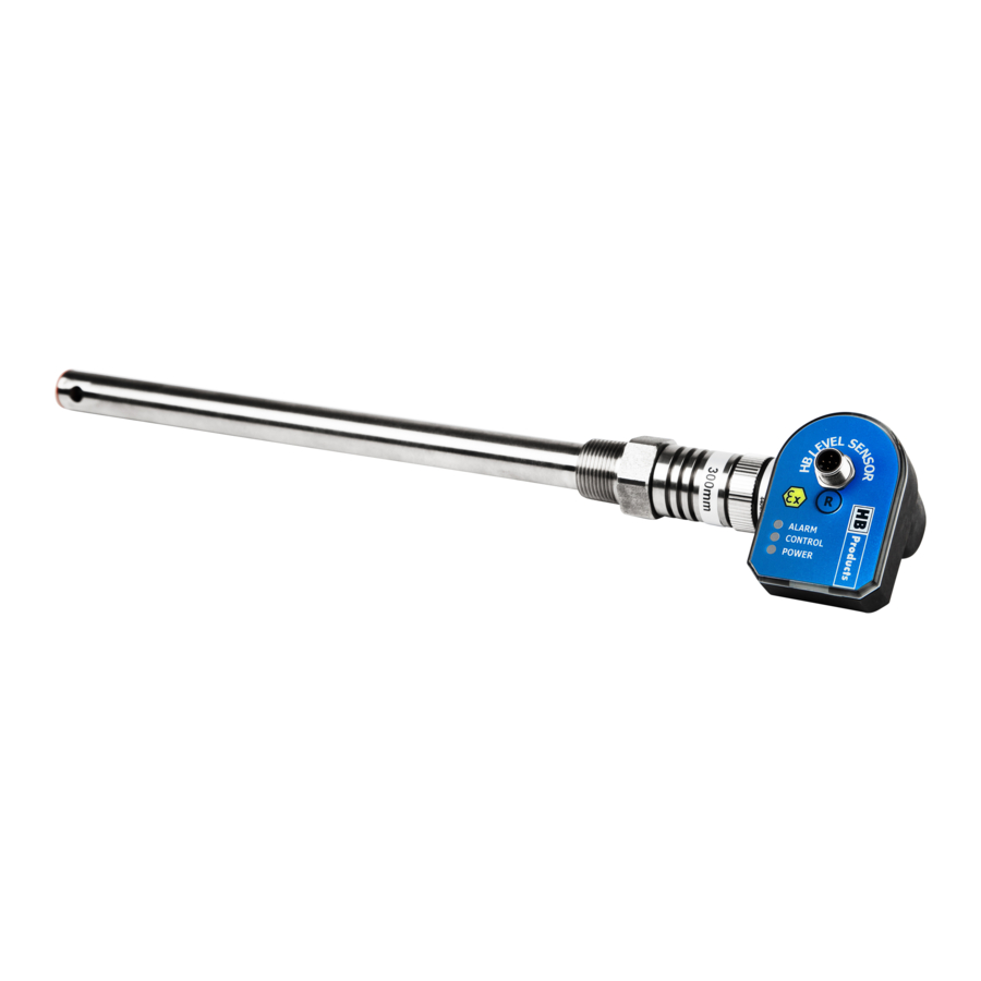
- Page 1 WE INCREASE UPTIME EFFICIENCY IN THE REFRIGERATION INDUSTRY Instruction manual HBLC-XXX-x-x – LEVEL SENSOR For analogue measurements of CO2 or HFC in refrigeration systems Instruction manual – HBLC-xxx – Levelsensor (005-UK) 1 / 11...
-
Page 2: Table Of Contents
WE INCREASE UPTIME EFFICIENCY IN THE REFRIGERATION INDUSTRY Table of contents Safety Instructions ................3 Introduction ..................4 Measurement Principle ..............4 Design and Function ................ 4 Technical data .................. 5 Application Examples ..............5 Installation Instructions ..............6 Power connection ................6 Installation guide ................ -
Page 3: Safety Instructions
If changes are made to type-approved equipment, this type approval becomes void. The product's input and output, as well as its accessories, may only be connected as shown in this guide. HB Products assumes no responsibility for damages resulting from not adhering to the above. -
Page 4: Introduction
When liquid covers the sensor, the measured calibration. capacity is changed. HB Products sensors are calibrated so that they differentiate between conductive and non-conductive liquids. In refrigeration systems, oil, HFC and liquid CO2 are not regarded as conductive fluids, whereas refrigerants such as ammonia and brine are regarded as conductive. -
Page 5: Technical Data
WE INCREASE UPTIME EFFICIENCY IN THE REFRIGERATION INDUSTRY Technical data Supply: Mechanical specifications: Supply: 24 V AC/DC ±10%* Thread connection: ¾” NPT & BSPP Current draw: Max 50 mA Materials - mechanical parts: AISI304/PTFE Plug: M12, 5 pins - Materials - electronic parts: Nylon 6 (PA) DIN 0627 Housing design: Front... -
Page 6: Installation Instructions
WE INCREASE UPTIME EFFICIENCY IN THE REFRIGERATION INDUSTRY Installation Instructions The following applies to the design of the system: It must be installed in a vertical position The sensor should be installed in a stand pipe where the flow stream and turbulence are minimised. -
Page 7: Installation Guide
WE INCREASE UPTIME EFFICIENCY IN THE REFRIGERATION INDUSTRY Installation guide The sensor is installed in standpipe or directly in the container. Liquid gasket is applied to the thread. To install the sensor, you must use a 2.5 mm Allen key, Loosen the two set screws that secure the electronic shifting spanner, and gasket, depending on the type of part and the mechanical part. -
Page 8: Led Indication
WE INCREASE UPTIME EFFICIENCY IN THE REFRIGERATION INDUSTRY LED indication LED indication: 1) Green LED indicates 24 V AC/DC supply (blinks during operation) 2) Yellow LED – in connection with calibration 3) Red LED indicates ALARM at 100% LED Signal ON/OFF/Frequency Functionality Green Supply... -
Page 9: Installation Of Hb Configurations Tool
WE INCREASE UPTIME EFFICIENCY IN THE REFRIGERATION INDUSTRY In case a smaller measurement area is desired, a recalibration can be performed. 6) Connect the PC Tool again and disconnect the calibration function in the tool. 7) Connect the power cable. Instruction for 100% calibration: 1) The sensors calibration function should be connected via the HB tool. -
Page 10: Sensor Repair
In case of faults with the sensor, it will typically be necessary to replace only the electronics. Sensor electronics are fully encapsulated and can therefore not be repaired. Complaint cases are handled by the HB products dealers/distributor. Consideration must be given to the complaint procedures before returning the sensor. -
Page 11: Spare Parts
HBLC-CO2-EL Further information’s For further information, please visit our website, www.hbproducts.dk or send an email to: support@hbproducts.dk HB Products A/S – Bøgekildevej 21 – DK8361 Hasselager – support@hbproducts.dk – www.hbproducts.dk Instruction manual – HBLC-xxx – Levelsensor (005-UK) 11 / 11...
Need help?
Do you have a question about the HBLC Series and is the answer not in the manual?
Questions and answers