Table of Contents
Advertisement
Quick Links
Advertisement
Table of Contents

Related Manuals for SUNSTONE PicoDC


Summary of Contents for SUNSTONE PicoDC
- Page 1 Picó Direct Current Resistance Welder Users Guide 20210615 • PART #1230...
- Page 2 ING LLC PRODUCT OR ANY THIRD PARTY PRODUCTS THAT ARE USED IN OR WITH THE SUNSTONE ENGINEERING LLC PRODUCT, OR LOSS OF USE OF THE SUNSTONE ENGINEERING LLC PRODUCT OR ANY THIRD PARTY PRODUCTS THAT ARE USED IN OR WITH THE SUNSTONE ENGINEERING LLC PRODUCT, EVEN IF SUNSTONE ENGINEERING LLC HAS BEEN ADVISED OF THE POSSIBILITY OF SUCH DAMAGES.
-
Page 3: Table Of Contents
e Micro Welder Experts Contents Chapter 1: Overview ............1 Position .............. 17 Welding Tips and Recommendations ....3 Timing ..............18 Common Electrode Types ........4 Speed ..............19 How to Maintain Repeatable Welds ....5 Displacement ........... 20 Chapter 2: Setup and Installation ......7 Weld Setting Screen Operation ...... - Page 4 Users Guide Picó...
-
Page 5: Chapter 1: Overview
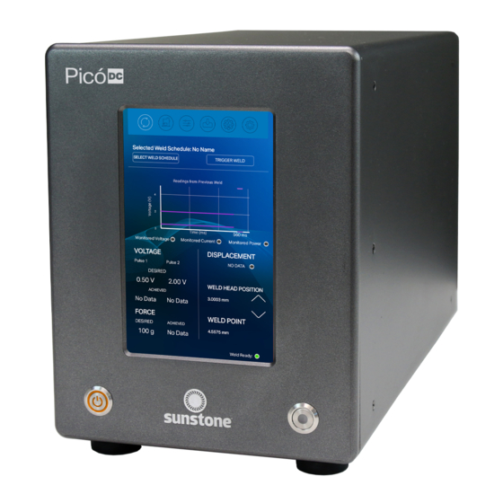
Micro Welder Experts Chapter 1: Overview The Sunstone Pico is a closed-loop feedback, direct-current, resistance welder engineered for thermocom- pression and other fine welds. With built-in force and displacement monitoring, the Pico provides unmatched precision, energy control, and monitoring using a color touchscreen interface. - Page 6 What is Direct Current Resistance Welding? The Sunstone Pico welder converts the AC power coming from the wall to DC power and utilizes an internal control system to regulate and maintain the weld discharge for accurate, repeatable welds. The control system allows for fine tuning and manipulation of the weld energy to adjust for various welding applications.
-
Page 7: Welding Tips And Recommendations
WELD ENERGY The weld energy is adjusted using the welding power supply. Sunstone recommends that you first try a weld at a low energy setting and then increase energy until the desired hold strength is achieved. This tactic helps pre- vent destroying the workpiece by having too much energy to start out. -
Page 8: Common Electrode Types
Picó Users Guide WELD LENGTH Some applications require longer weld times than others to achieve good welds. Keep in mind that the longer the weld lasts, the larger the heat affected zone will become. Weld length plays an important role in Thermo- compression welding because the electrode tip must remain heated long enough for the coating and wire to melt. -
Page 9: How To Maintain Repeatable Welds
e Micro Welder Experts Common Electrode Configurations Direct weld (Opposed) Current passes from one electrode through both workpieces and out the opposing electrode. Typically the easiest configuration to achieve good weld nuggets and strength. See Figure 5.1. Figure 5.1. Direct Figure 5.2. - Page 10 Picó Users Guide • Measured gap distances (between electrodes, between the tips and workpiece, etc) • Electrode placement in electrode holders (flush with top, extending “X” amount, etc.) • Welding Power Supply settings (energy, length, etc.) • Make sure there are no impediments to shaft movement. •...
-
Page 11: Chapter 2: Setup And Installation
Voltage and Power Requirements The Sunstone Pico DC welder can be used with either 110VAC or 220VAC input voltage. The voltage is auto- matically detected by the welder so no voltage selection is required prior to connecting and powering up. -
Page 12: Exploring The Welder's Front Panel
Picó Users Guide What’s in the Box • Pico DC Welder • 90-250VAC Power Cord • Foot Pedal • Users Guide • Safety Guide Exploring the Welder’s Front Panel The front of the welder (see figure 8.1) consists of three components: the digital Touchscreen (A), the Power Button (B), and the Weld On/Off Button (C). -
Page 13: Exploring The Welder's Back Panel
e Micro Welder Experts Exploring the Welder’s Back Panel On the back panel of the Pico you’ll find identifying details such as model and serial numbers as well as certification marks. The following components can also be found on the back panel, as shown in Figure 9.1 (see also Appendix A, page 34 about connector pinouts): Ethernet Port The Ethernet Port (A) allows you to connect the Pico... -
Page 14: Exploring The Side Panel
Picó Users Guide Secondary Trigger Use the Secondary Trigger Port (G) to connect a foot pedal, or other switch, to initiate a weld. Positive and Negative Weld Terminals Use the Positive and Negative Weld Terminals (H) to connect the weld cables from a weld head or hand at- tachment to the Pico to deliver weld energy. -
Page 15: How To Set Up Your Welder
• Connect the Weld Head Control cable (if using the Sunstone Micro E weld head) to the Weld Figure 11.1. Unbox the Pico and make sure these basic connections are completed: Power Head Control Port (D). -
Page 16: Chapter 3: How To Use The Software Interface
Picó Users Guide Chapter 3: How to Use the Pico Software Interface The Pico’s secret sauce is its digital interface. The Pico lets you set energy, force, displacement, timing, and oth- er weld parameters to an exact number, something you can’t do with other welders. In this chapter you’ll learn how the software is organized and how to use each feature. -
Page 17: Run Screen Operation
e Micro Welder Experts Save/Load Screen (D) Touch the Save/Load Screen icon (D) to save weld settings or load weld settings from a previously saved weld. See page 23. Communications Screen (E) Touch the Communications Screen icon (C) to access PLC controls for automation, settings for alarms, and features for importing/exporting pre-set welds. -
Page 18: Comparator Monitoring
Picó Users Guide WAVEFORM DISPLAY SECTION (K) A graph (K) at the top of the Run Screen in Figure 13.1 displays a visual representation of the last recorded weld discharge. Weld voltage/current/power (dependent on what is selected in the comparator screen) is displayed on the Y axis, and weld discharge length (time) is displayed on the X axis. -
Page 19: Weld Head Control Screen Operation
Micro Welder Experts settings and connections. Verify that the Weld On/Off button is in the on state. If you need assistance, call the Sunstone Customer Service team at +1 801-658-0015 or send a message to support@sunstonewelders.com. Weld Head Control Screen... -
Page 20: Force
Picó Users Guide the workpiece. Once the desired force is met, the weld process is triggered. Upon completion of the sequence, the weld head will return to the Home Position, ready for the operator to initiate the next weld. User config- ured parameters of the Direct Control weld sequence include Force, Timing, and Displacement. -
Page 21: Position
e Micro Welder Experts In Automatic Control, calibration will need to be com- pleted first. After changing the target force, the Auto Set button on the Position Screen (see Figure 17.1) can be used to calibrate the force. Once the play button is pressed, the weld head will travel to the part, set the Weld Point and Hover Point, then calibrate the force. -
Page 22: Timing
Picó Users Guide Press the forward arrow button at the bottom of the screen to advance to the next weld head setup step. You can always end the setup process by pressing the Close Button. TIMING The fourth step in setting up the weld head is to set the desired Squeeze Time and Hold Time. -
Page 23: Speed
e Micro Welder Experts SPEED The fifth step in setting up the weld head is to set desired travel speeds, which can be individually set for transitions between three different points during the weld via three different sliders. Speeds can be set within the range of 1 to 100%. -
Page 24: Displacement
Picó Users Guide DISPLACEMENT The sixth and final step in setting up the weld head is to set a minimum and maximum value for weld displacement (the distance the electrode travels during the weld energy discharge). If you wish to set a minimum and maximum displace- ment limit, touch and slide the Displacement On/Off Button to the On position. -
Page 25: Weld Setting Screen Operation
e Micro Welder Experts Weld Settings Screen Operation The Weld Settings Screen is used to set the desired voltage and duration of the weld discharge. The Pico can be configured to release two independently set pulses of weld energy with customizable pre-weld delay and delay between pulses. -
Page 26: Set Pulse Duration
Picó Users Guide Pulse 1 voltage is generally less than Pulse 2 voltage. To help determine ideal Pulse 1 settings, turn off Pulse 2 and do a series of test welds starting at a low voltage setting. Increase the voltage about 3% each test until the welded parts barely stick together. -
Page 27: Save/Load Screen Operation
e Micro Welder Experts Save/Load Screen Operation The Save/Load screen allows you to save and load weld schedules. See Figure 23.1. A weld schedule is the collection of all settings for a particular weld, such as energy levels, delays, number of puls- es, etc. -
Page 28: Communications Screen Operation
Picó Users Guide • Edit the name and or notes. • Press the Save Over Selected Weld Button (G). • A message will pop up on the screen asking for confirmation before allowing the weld to be edited and saved. To load an existing weld schedule: •... - Page 29 e Micro Welder Experts which operators can choose (pins 3, 4, 7, and 8). The pins are labeled 1-8 and each has a color coded box (C). Blue boxes indicate the pin is used for inputs, while orange boxes indicate outputs. Some pins have a color cod- ed circle (D) on the right side.
- Page 30 Picó Users Guide Remote Schedule Select The Remote Schedule Select feature allows you to pro- gram up to four pre-saved schedules, recall them, and switch between them via the built in PLC capabilities. To do so, press the Remote Schedule Select Button (A), as seen in Figure 26.1.
-
Page 31: Alarms
e Micro Welder Experts ALARMS To access the Pico alarms control panel, press the Alarms Button (A) in the Communications Screen, as shown in Figure 27.1. The Alarms control panel will display certain power supply statuses, active warnings, active alarms, and other alarm-related settings. The top portion of the screen displays Current Val- ues (B) for temperature, comparator failures in a row, displacement failures in a row and weld count. -
Page 32: Importing/Exporting Weld Settings
Picó Users Guide Note: If a warning and its corresponding alarm are both enabled and active, then only the alarm will be displayed. Warnings are active until the corresponding alarm is also active. Active warnings and alarms can be cleared and reset by toggling the switch next to the alarm or by using the PLC inputs (Pin 3 or Pin 4). -
Page 33: Systems Screen Operation
e Micro Welder Experts port Welds feature does not copy system settings from one welder to another, only weld schedules. Import Saved Welds (G) After you’ve exported saved weld schedules using the Export Welds feature, use the Import Welds feature to import the files from a USB drive to the welder. -
Page 34: Lock Panel
Operators can dismiss the message or navigate directly to the lock screen where the PIN can be input to unlock the welder. If a PIN is forgotten, call Sunstone Customer Service at +1 801-658-0015 for assistance. 30 • Questions? Call or Text +1-801-658-0015... -
Page 35: System Panel
Enter Test Suite (I) The Test Suite is helpful for diagnostics and technical support and can only be accessed with a password. Contact Sunstone Support if this password is needed. System Information (J) System Information (J) is displayed at the bottom of the Settings Screen. -
Page 36: How To Update The Pico's Software
How to Update the Pico’s Software The Sunstone Pico software will be updated from time to time as needed. The software can be updated directly from the welder via Wi-Fi or the update can be downloaded to a USB storage device and plugged into the weld- er for updating. - Page 37 Follow the on-screen prompts. • Once the update is complete, the welder will display an error message, which can be ignored—don’t call Sunstone Customer Service. Continue to the next bullet point. • Turn the welder off and wait 10 seconds.
-
Page 38: Appendix A: Pinout Details
Picó Users Guide Appendix A: Pinout Details The following information details the Pico’s DIN connections, displayed here as if viewed from the pack panel. Refer to Appendix A for pinout configurations. The PLC port (see Figure 34.1) mates to SD-80LP, used to connect PLC for basic functions, such as the following: GND/Shield +12V Current Limited... - Page 39 e Micro Welder Experts WH Control The WH Control port (see Figure 35.1) mates to SD-40LP. At time of publication, this port is not configured; could be used to control pneumatic head with future upgrade. GND/Shield Weld Head Actuation 1. +12VDC(0.5A Max) is sent when weld head needs to actuate.
-
Page 40: Product Specifications
Picó Users Guide KEY UNIT SPECIFICATIONS TABLETOP FOOTPRINT (L X W X H) 22.4x48.2x30.5 cm UNIT WEIGHT 19.6 kg INPUT VOLTAGE (SINGLE PHASE) 90-264 VAC FREQUENCY RANGE 47-63 Hz POWER FACTOR (TYP.) 0.95/230 VAC (0.98/115 VAC at Full Load) OUTPUT VOLTAGE RANGE 0.10-5.00 V (0.01 V Intervals) OUTPUT CURRENT RANGE 10.0-250 A... - Page 41 e Micro Welder Experts Questions? Call or Text +1-801-658-0015 • 37...
- Page 42 Picó Users Guide 38 • Questions? Call or Text +1-801-658-0015...
- Page 43 e Micro Welder Experts Questions? Call or Text +1-801-658-0015 • 39...
- Page 44 ©2020 Sunstone Engineering LLC. Sunstone and Sunstone Circle are trademarks of Sunstone Engineering LLC. Conditions and restrictions apply. Ask for details or visit www.suntonewelders.com/sunstonecircle for complete terms of service. Sunstone Engineering LLC reserves the right to change, alter, modify, or cancel this program at any time.
- Page 45 Expedited Customer More Valuable Upgrades Shipping Service Member Benefits! When your welder is Should your Sunstone At Sunstone every You’ll receive snazzy powered by the latest welder ever need repair, customer is a VIP, but when Sunstone swag, a software improvements we’ll cover the shipping...
- Page 46 1693 American Way Ste 5 • Payson UT 84651 USA Tel. +1-801-658-0015 wwww.sunstonewelders.com PART #1230 ©2021 Sunstone Engineering LLC. Safety information subject to change. Sunstone and Orion are trademarks of Sunstone Engineering LLC. 20210615 •...
Need help?
Do you have a question about the PicoDC and is the answer not in the manual?
Questions and answers