Table of Contents
Advertisement
Quick Links
Advertisement
Table of Contents

Related Manuals for SUNSTONE Linear DC


Summary of Contents for SUNSTONE Linear DC
- Page 1 Sunstone Welders Linear DC User Manual...
-
Page 2: Table Of Contents
Table of Contents Chapter 1: Introduction Chapter 8: Data Specifications Quick Look Chapter 2: Getting Started Chapter 9: Safety Set-up Linear DC Connecting Welding Attachments Precautions Chapter 3: Interface Operational Controls Settings Button Save Button Load Button Video Tab Schedules Tab... -
Page 3: Chapter 1: Introduction
Thank you for choosing Sunstone Welders and congratulations on your purchase! You are now the proud owner of a Sunstone Linear DC Welder. This manual was designed to have you welding safely within minutes of unpacking your new welder. Please read and follow all safety precautions before proceeding with the welding process. -
Page 4: Quick Look
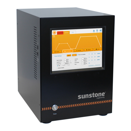
Quick Look TOUCH SCREEN INTERFACE Set all weld parameters here. USB PORT Upload software updates. POWER BUTTON Press to power up. WELDER INFO Welder information is found here. (-) (+) TERMINALS Connect weld head or welding attachments cables COOLING FANS here. -
Page 5: Set-Up Linear Dc
Quick Start Guide SPACE REQUIREMENTS The Linear DC has a 15.2”x11.4” footprint. Be sure to provide enough space to connect a weld head or welding hand attachment and roughly a 2-4” space on the backside of the unit to connect power and weld attachment cables. -
Page 6: Connecting Welding Attachments
CONNECT WELDING ATTACHMENTS Sunstone Weld Head - automatic weld triggering 1. Connect weld head cables to negative and positive terminals on the back of the Linear DC. 2. Connect weld head actuation cable to “Weld Head Actuation” DIN connection port on the back of the welder. -
Page 7: Precautions
Sunstone Micro Weld Head - dual foot pedal triggering 1. Connect weld head cables to negative and positive terminals on the back of the Linear DC. 2. Connect included Linear DC foot pedal into “Weld Discharge Trigger” DIN connection port on the back of the welder. - Page 8 Ensure Emergency Stop Switch is working WARNING: THIS MUST BE DONE PRIOR TO OPERATING WELDER In order to verify that the emergency stop switch is working properly, plug in the included emergency stop push button into the 3DIN connector on the back panel. Plug the welder into AC power.
-
Page 9: Chapter 3: Interface
Operational Controls NUMERIC KEYPAD AND SLIDER BAR The Linear DC touch screen display features a numeric keypad with a build in slider bar for easy setting of weld parameters. Users simply touch the weld setting boxes on the display and then either type in their desired parameter in the numeric keypad or slide their finger on the slider bar to move the weld parameter value up or down. -
Page 10: Settings Button
UPDATE WELDER As software updates become available, user can download them from the resource page on the Sunstone website. Once the update is downloaded and place in th root directory of the USB thumb drive follow the steps below. 1. Insert the USB stick into the USB slot on the side of the welder. -
Page 11: Save Button
Save Button Touch the Save Button to create a custom weld parameter. This feature will save all the current weld parameter settings. After touching the save button follow these steps: 1. Type in a name for the new setting or choose an existing saved setting on the left and it will be replaced with the current setting. -
Page 12: Load Button
Load Button Touch the Load Button to open previously saved weld parameters. Simply scroll through the options on the left of the screen then select the desired previously saved weld parameter. Then touch the load button. -
Page 13: Video Tab
Videos Tab Select from the tabs on the left to watch promotional, settings, and technique videos. -
Page 14: Schedules Tab
Schedules Tab PRECHECK SCREEN The Linear DC is equipped with an optional “Precheck” feature that enables the welder to test the resistance of the weld path before a weld is performed. This allows the weld controller to notify the user if the chosen weld parameters are attainable with the connected weld path resistance. - Page 15 Voltage • - This displays how much voltage will be applied during the precheck. Generally these values should be low to avoid discharging significant amounts of energy into the weld path. Min Current Max Current • - To ensure that too much or too little energy is not discharged into the weld path during the “Precheck”, the user can define a maximum and a minimum allowable current.
- Page 16 PULSE SETTINGS SCREEN Unit Selector • - The welder can control the pulse in terms of Current, Voltage, or Power. Before making any setting, select the desired unit of power. Single and Dual Pulse Description • - Single pulse welds are typically used where the work pieces are fairly clean.
- Page 17 use the slider adjustment bar under the numeric key pad to enter desired values. The image displayed on the screen above the Pulse 1 parameters shows a representation of what the pulse 1 waveform looks like. After setting the Pulse 1 parameters select the Pulse 2 button and select the Pulse 2 desired settings.
- Page 18 COMPARATOR SCREEN This screen is used when monitoring is enabled on the “Pulse Settings” Screen. However users have the capability to turn the function on or off. Desired (voltage, current, or power) • - This displays the desired (voltage, current, or power) that has been selected on the “Pulse Settings”...
- Page 19 Do nothing - The welder will continue operation as normal even when the previous (voltage, current, or power) were out of the min max range. Flag and stop weld - The welder will stop welding and alert the user anytime the (voltage, current, or power) goes out of the min max range that was set.
- Page 20 Disabled - Select this when using a hand piece. Manual - Select this when controlling a weld head and the Linear DC with two separate foot pedals. Automatic - Select this when controlling a weld head and the Linear DC with one foot pedal or when attaching to a PLC.
- Page 21 it has reached the set force. Pre-Weld Delay • - The time the weld head will wait to begin moving after receiving a weld signal from the foot pedal or PLC Squeeze Time • - The time the weld head will wait to start the actual weld after having made contact with the piece.
- Page 22 CONTROL SCREEN There are two start trigger options. One must be selected before entering welding parameters. Foot Pedal - Controlled by user pressing the foot pedal. PLC Controlled - Controlled by user using a PLC (Programmable Logic Controller).
-
Page 23: Operational States Button
Operational States Button The operational states tab is next to the schedules tab and displays the welders current status. Below is a description of each status. Remember that some of these flash by so quickly that they may not be seen, but we will give a description of each. The main purpose and functionality of this button is to change from “weld on”... - Page 24 this state when a weld trigger signal is received or when the user touches the “WELD” button. The welder enters this state when the user touches the “NO WELD” button or after a welding and/or charging sequence has occurred. WELDING Transition to this state happens from the WELD state when a trigger signal is received.
- Page 25 continue normally until the user clears the error. EMERGENCY STOP For safety reasons this state is used to suspend all charging and welding functions and discharge all stored energy in the welder as quickly as possible. This state is activated by the user when the external emergency stop signal is sent to the welder, or when the welder detects specific conditions.
-
Page 26: Chapter 4: Start Welding
Chapter 4: Start Welding Example Project Setup Below is an example project we preformed welding a piece of Nitinol Foil to a Tantalum plate. PRECHECK PULSE 1 SETTINGS... - Page 27 COMPARATOR WELD HEAD...
-
Page 28: Perform A Weld
10ms. These settings will likely not produce a quality weld; but they will serve as a good place to start. 3. With the Linear DC in a “no weld” state, check the part height. Check for obstructions or anything that could short between (+) and (-) electrodes. - Page 29 9. If using a separate foot pedal to trigger the weld, press the foot pedal to trigger a weld output from the welder. 10. Inspect the weld and adjust weld parameters accordingly. Keep in mind that the effect that voltage has on a weld is not linear (i.e. a weld made at 4 volts is not twice as powerful as a weld made at 2 volts.
-
Page 30: Chapter 5: Automated Welding
Chapter 5: Automated Welding Overview The Linear DC Basic welding unit has been designed to be able to be integrated into automated welding systems. To aid in this integration the welder has the ability to output a series of sensing inputs, control output signals, and notification signals. - Page 31 Basic PLC Trigger Input: This input gives an automated weld delivery system the ability to notify the Linear DC welding unit when to trigger a welding sequence. This signal can be controlled and delivered by other automation system components such as a PLC. The user interface provides triggering options for when this signal is active.
-
Page 32: Chapter 6: Resistance Welding Basics
Chapter 6: Resistance Welding Basics Overview SINGLE AND DUAL PULSE DESCRIPTION Single pulse welds are typically used where the work pieces are fairly clean. Single pulse welds are often beneficial when welding small parts such as fine wires where very low heat is required. Dual pulse welds are helpful when the piece is dirty, or has oxides/plating on it. - Page 33 WELDING ATTACHMENTS Weld heads or welding hand attachments will be chosen based on electrode access, and the type of application. When both sides (top and bottom) of the work piece can be accessed, an OPPOSED type weld head or welding hand attachment is ideal. When the user only has access to one side of the work piece, either a PARALLEL weld head or a welding hand attachment can be used.
-
Page 34: Chapter 7: Technical Assistanc
Chapter 7: Technical Assistance For technical assistance or part replacement contact: Sunstone 1693 American Way Suite #5 Payson, UT 84651 +1-801-658-0015 (international) 1.877.786.9353 (toll free) tech@SunstoneWelders.com SOFTWARE In rare circumstances a warning message may pop-up and warn that the unit is having an issue. - Page 35 Chapter 8: Data Specifications Linear DC Voltage (Single Phase) 90 - 264 AC Version Power Source 110 or 220 Single Phase Current 10 - 4000A 10 Amp/Step Voltage 0.1 - 10.0V at 10mV/Step Power 0.01 - 20kW at 10W/Step Peak Current...
- Page 36 THE MANUFACTURER SHOULD SERVICE THE UNIT. Use only genuine replacement parts from the manufacturer. **Contact Sunstone Engineering before opening the unit for any reason** SAFETY PRECAUTIONS The below safety advice is generalized advice for the welding industry. These safety precautions are not all inclusive.
- Page 37 • Do not exceed the equipment’s rated capacity. • Use only correct fuses or circuit breakers. Do not oversize or bypass them. SAFETY PRECAUTIONS FOR ELECTRICAL SHOCK Touching live electrical parts can cause fatal shocks or severe burns. Incorrectly installed or improperly grounded equipment is a hazard.
- Page 38 Welding can produce fumes and gases. Breathing these fumes and gases can be hazardous to your health. Sunstone weld heads produce minimal fumes and gases when compared to large- scale weld heads. Though not required, some form of ventilation is recommended.
- Page 39 instructions for metals, consumables, coatings, cleaners, and degreasers. • Do not weld in locations near degreasing, cleaning, or spraying operations. The heat and rays of the weld can react with vapors to form highly toxic and irritating gases. • Do not weld on coated metals, such as galvanized, lead, or cadmium-plated steel, unless the coating is removed from the weld area, the work area is well ventilated, and the operator is wearing an air-supplied respirator.
- Page 40 Regulations (CFR), Part 1910, Subpart Q, and Part 1926, Subpart J, from U.S. Government Printing Office, Superintendent of Documents, P.O. Box 371954, Pittsburgh, PA 5250-7954 (phone: 1-866- 512-1800) (there are 10 Regional Offices—phone for Region 5, Chicago, is 312-353-2220, website: www.osha.gov).
- Page 42 SUNSTONE ENGINEERING R&D CORPORATION 1693 American Way Suite #5 Payson, UT 84651 1.877.786.9353 (toll free) +1-801-658-0015 (international) SunstoneWelders.com...
Need help?
Do you have a question about the Linear DC and is the answer not in the manual?
Questions and answers