
Related Manuals for SUNSTONE CDDP-A


Summary of Contents for SUNSTONE CDDP-A
- Page 1 CDDP-A User Manual Advanced Capacitive Discharge Dual Pulse Welder For Models 200Ws, 400Ws, 600Ws, 1200Ws Version 20210101 • Part #1176...
- Page 2 INCIDENTAL, CONSEQUENTIAL, SPECIAL, EXEMPLARY OR PUNITIVE DAMAGES, OF ANY NATURE WHAT- SOEVER, ARISING OUT OF THE USE OF OR INABILITY TO USE ANY SUNSTONE ENGINEERING LLC PROD- UCT, INCLUDING, WITHOUT LIMITATION, PROPERTY DAMAGE, LOSS OF VALUE OF THE SUNSTONE ENGI-...
-
Page 3: Table Of Contents
Using the Modbus Server Tester....... 36 Settings Screen ............12 Setup the Computer/PLC ........36 Retrieving information from the CDDP-A ..37 Chapter 4: Home Screen Operation ....13 Sending Information to the CDDP-A ....38 Waveform Display ........... 13 Reading the Output Wwindow ...... - Page 4 Network Info (20 x 16 bit Registers) ....80 Comparator Results ..........68 Modbus Exception Codes ........81 File Records ............... 68 Raw Data (Example) .......... 68 CDDP-A Data Specifications Table ....83 iv • Questions? Call or Text +1-801-658-0015...
-
Page 5: Chapter 1: Overview
Chapter 1: Overview Features Sunstone’s advanced dual pulse CD welders offer many capabilities including weld monitoring, SPC tools, and a large capacitive touch-screen interface. The touch-screen interface provides easy access to all weld parameters. In addition, you get a visual of the weld waveform graph, weld histograms, alarms, warnings, and even on-screen documents and videos. -
Page 6: What Is Cd Welding
SUNSTONE CDDP-A USERS GUIDE The key features of the Sunstone CDDP-A are as follows: • Touch-screen interface • Microprocessor controlled operation • Dual pulse • Weld monitoring of peak currents • Monitor limits with logic (inhibit second pulse) • Weld head controls •... -
Page 7: Weld Formation
Micro Welder Experts the first few milliseconds of the welding process. Sunstone’s proprietary technology allows the energy to be discharged with very high peak currents, as seen in Figure 3.1 to produce the best weld nuggets. This technology is not only designed to increase the energy delivered for weld formation but to also minimize the heat that is spread to the surrounding material. -
Page 8: Electrode Configurations
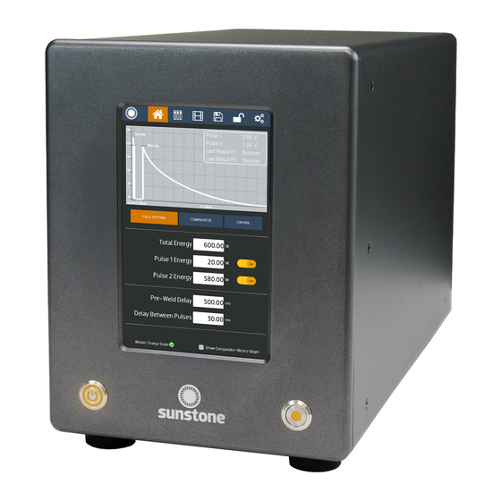
Current is divided between the two parts. This weld configuration requires more weld energy. WELD ENERGY Sunstone capacitive discharge dual pulse welders allow adjust- ment of the stored energy via the touch screen user interface, shown in FIGURE 4. The energy is then displayed in watt sec- onds (Joules) as a waveform graph on the user interface LCD display. -
Page 9: Chapter 2: Setup And Installation
Keep the working area clear of excessive dust, acids, corrosive gases, salt, and any moisture. VOLTAGE AND POWER REQUIREMENTS The Sunstone CDDP-A welder is equipped with universal power supplies and can be used with either 110VAC or 220VAC. No voltage selection is required prior to connecting and powering on the welder. The welder will automatically detect the voltage and make the appropriate adjustments automatically. -
Page 10: Weld Actuation
WELD ACTUATION Figure 6.1.External trigger wiring diagram. N.O. is short for “Normally Open.”. The CDDP-A welder is actuated by means of an external trigger port located on the back of the welder (see Figure 7.1). The trig- N.O. Circuit ger uses a 3 DIN connector and requires shielded wire. Figure N.O. - Page 11 Micro Welder Experts Figure 7.1. On the back of the CDDP-A is where you’ll find all connections to power, weld heads, triggers, and more. Ethernet Port Accessory Port PLC Port E-stop Weld Head Control Primary Trigger Negative Weld Terminal...
-
Page 12: Exploring The Side Panel
SUNSTONE CDDP-A USERS GUIDE The Weld Head Control is used to send a trigger signal to a weld head. The Primary Trigger is used to connect a foot pedal, or other switch, to initiate a weld. The Secondary Trigger is used to connect a foot pedal, or other switch, to initiate a weld. - Page 13 Micro Welder Experts • Determine which weld trigger configuration is best for your setup. Options include: • Pneumatic weld head controlled by the CDDP-A welder. • Fully manual operation • Auto with Timing option • Fully Automatic option •...
-
Page 14: Chapter 3: User Interface Overview
Communications Screen. PLC. A Sunstone CDDP-A PLC’s capabilities were designed to be used with a Probotix or Janome robotic table. Use this screen to enter the necessary instructions to control the table. See Chapter 5 for PLC instructions. -
Page 15: Media
Media Screen. details about the Communications Screen. Alarms. You are able to instruct the Sunstone CDDP-A to alert you to temperature fluctuations, comparator failures, electrode sticks, and more. Import/Export. You are able to import or export weld settings from one CDDP-A welder to another. -
Page 16: Lock Screen
See Chapter 8 for more information. LOCK SCREEN The Sunstone CDDP-A allows the operator to lock the welder, preventing others from using the welder or pre- venting others from changing the welder’s settings. See Chapter 8 for specific details about elements of the Lock Screen. -
Page 17: Chapter 4: Home Screen Operation
e Micro Welder Experts Chapter 4: Home Screen Operation The Home Screen is where the operator controls all aspects relating to the weld energy, waveform, and timing delays. During operation, the Home Screen will be accessed more than any other screen. Waveform Display The Waveform displays a graphical representation of the settings determined for each weld parameters. -
Page 18: Pulse Settings
Pulse 2 of 20Ws. Pulse 1 and Pulse 2 Sunstone dual pulse welders have two pulse width energy controls. Each pulse can be adjusted separately or turned off if desired. Pulse 1 is adjustable between 0.1WS and 30% of Total Stored Energy. - Page 19 ‘pops’ off without tearing, more energy should be used. Thicker materials should be pulled with a specific pull force requirement in mind. Each Sunstone welder is fully adjustable between its minimum and maximum energy. Sunstone capacitive dual pulse welders have weld repetition rates of up to 650 welds/min. See page 88 for additional details on weld repetition rates.
-
Page 20: Comparator
SUNSTONE CDDP-A USERS GUIDE Comparator The Comparator Screen can be used to monitor the peak weld values of the previous welds. The welder can monitor the peak voltage, peak current, and peak power simultaneously. Both Pulse 1 and Pulse 2 can be monitored. - Page 21 e Micro Welder Experts If Pulse 1 is found to be outside of the limits, operators can choose to continue to Pulse 2, or stop the weld and inhibit pulse 2. To do so, toggle the “Continue on Failure” button. The results section near the bottom of the screen shows the results of past welds.
-
Page 22: Control
Hold time is used in this mode to control how long the weld head stays descended after the weld energy is released. See the Sunstone weld head users guide for more information. -
Page 23: Timing Diagrams
e Micro Welder Experts Primary Trigger Primary Trigger Weld Ready Weld Ready WeldHead WeldHead Secondary Trigger Secondary Trigger Alarm Alarm Warning Warning Weld Pulses Weld Pulses Pulse 1 Pulse 2 Cool Figure 19.1. Sample timing diagram for Fully Manual scenario. TIMING DIAGRAMS The following timing diagrams are included to help visualize all the different steps involved when making welds. - Page 24 SUNSTONE CDDP-A USERS GUIDE Primary Trigger Primary Trigger Weld Ready Weld Ready WeldHead WeldHead Alarm Alarm Warning Warning Weld Pulses Weld Pulses Pulse 1 Cool Pulse 2 Hold Pre-Weld Figure 20.1. Sample timing diagram for Auto with Timing and Auto with Trigger scenarios.
- Page 25 e Micro Welder Experts Auto with Trigger Refer to Figure 20.1. D1: A delay that occurs from the time primary trigger is triggered and the weld ready signal changes to a low value. Typical time for this is between 1 and 50 milliseconds. Pre-Weld: An operator-defined delay that happens before the signal to the weld head is sent.
-
Page 26: Chapter 5: Plc Automation Features
SUNSTONE CDDP-A USERS GUIDE Chapter 5: PLC Automation Features Select the Communications Screen icon in the Navigation Bar to access all CDDP-A automation features. The Communications Screen has three sub sections: the PLC tab, the Alarms tab, and the Import/Export tab. -
Page 27: Remote Schedule Select
Alarm: Wrong trigger detected Figure 23.1. Use the Communications Screen • Alarm: Trigger in No Weld State to access all CDDP-A automation features. The • Alarm: Part Check Failed Communications Screen has three sub sections: the PLC tab, the Alarms tab, and the Import/Export •... -
Page 28: Alarms Tab
SUNSTONE CDDP-A USERS GUIDE To select pre-saved schedules, click on the drop down menus and select the desired saved schedule. Operators can choose 4 different schedules that are selectable through the two PLC input pins on the 8DIN connector on the back panel. These will be passed in using a bit mapping. -
Page 29: Import/Export Tab
e Micro Welder Experts Import/Export Tab The Import/Export tab has six buttons that can be used for dif- ferent import and export functions. See Figure 25.1. Export History will export the past weld results history to a USB stick. The export CSV file will include all weld parameters and comparator values. -
Page 30: Chapter 6: How To Use Media Features
Chapter 6: How to Use the CDDP-A’s Media Features The Sunstone CDDP-A’s Media feature allows the operator to access application videos, training videos, and PDF documents. To access the Media Screen, click on the Media button in the Navigation Bar. The Media Screen opens as shown in Figure 27.1. - Page 31 e Micro Welder Experts Figure 27.1. Click on the Media icon in the Figure 27.2. When you select the Import/ Figure 27.3. When you select the Import/ Navigation Bar to open the Media Screen. Export tab will be able to export history, Export tab will be able to export history, export clone information for another welder, export clone information for another welder,...
-
Page 32: Chapter 7: How To Save And Load Weld Schedules
Over Selected Weld” button. A message will popup on the screen asking for confirmation before allowing the weld to be edited and saved. Figure 28.1. With the Sunstone CDDP-A you can save a particular weld schedule and retrieve it at any time. - Page 33 e Micro Welder Experts To delete an existing weld schedule, tap on the previously saved schedule and then tap the “Delete Selected Weld” button. A message will popup on the screen asking for confirmation before deleting the weld schedule. If an operator attempts to save a new schedule with the same name as a previously saved schedule, a mes- sage will popup to notify the operator that a “(1)”...
-
Page 34: Chapter 8: Lock Screen
Tap on the desired option and follow the screen prompts. The options include: Full Lockout, Limited Lockout, Change PIN, and Cancel. • The CDDP-A will ask for you to enter a PIN (Personal Identification Number) when you select Full Lockout, 30 • Questions? Call or Text +1-801-658-0015... - Page 35 PIN can be input to unlock the welder. If you forget your PIN call Sunstone Customer Service for assistance. Questions? Call or Text +1-801-658-0015 • 31...
-
Page 36: Chapter 9: How To Make System Changes
Enter Test Suite. The Test Suite is helpful for diagnostics and settings. technical support and can only be accessed with a password. Contact Sunstone Support if this password is needed. The System information is displayed at the bottom of the Set- tings Screen. -
Page 37: Chapter 10: How To Update The Welder's Software
Micro Welder Experts Chapter 10: How to Update the Welder’s Software The Sunstone CDDP-A software is updated from time to time as needed. You can update the software using a USB storage device or via a Wi-Fi connection. Note: Software updates are made available to Sunstone Circle customers. To learn more about the Sunstone Circle, visit www.sunstonewelders.com/circle or call 801-658-0015. - Page 38 SUNSTONE CDDP-A USERS GUIDE • Tap the “Update over Wi-Fi” button. If the welder is not connected to a network a popup message will appear. The popup window will display all the available networks and allow you to choose from one of them.
-
Page 39: Chapter 11: How To Configure An Ethernet Connection
Chapter 11: How to Configure an Ethernet Connection The Sunstone CDDP-A welder can be connected to and controlled by a computer using an Ethernet connec- tion. A Sunstone weld head connected to the welder can also be controlled by this connection. Follow the instructions below to setup and configure the Ethernet connection. -
Page 40: Using The Modbus Server Tester
CDDP-A. You can enter up to six IP addresses that will be allowed to connect to the CDDP-A. If you wish to view a list of what devises are already connected to the welder, press the Connected Devices button. -
Page 41: Retrieving Information From The Cddp-A
Appendix C, the Read Coils Table on page 65, you will see that the table defines what coil is pulled from the CDDP-A when reading from coils 0 through 23. If you Figure 37.2. Send Frame icon. choose “0000” as the starting address and “0001” as... -
Page 42: Sending Information To The Cddp-A
“Write Single Coil” function. If you go further into the Modbus document you will find a Coils Table on page 61 that defines what coil is written to the CDDP-A when writing to coils 0 through 23. If you choose “0000” as the output address and “ON”... -
Page 43: Reading The Output Wwindow
e Micro Welder Experts • Click the Send button. • The request you just entered will be displayed in the main window of the Modbus Server Tester app, along with a response. Both the request and response should match, as highlighted in Figure 39.1. The 0xFF signi- fies that a “ON”... -
Page 44: How To Read/Write To A Holding Register
0x25D2 converts to 9682mV or 9.682V. Conse- Figure 40.1. quently, if you look at the CDDP-A’s Home screen and weld form graph (see Figure 40.3), notice that the peak is close to 9.6V, so 9.682V is correct. - Page 45 e Micro Welder Experts those into the inputs, as shown in Figure 41.1. Click Finish. The Modbus Server Tester output window appears. Looking at the output window, you will see that the request had 0x0203A0 and that the response was valid, as highlighted in Figure 41.2.
-
Page 46: Retrieving General Information From The Cddp-A
XX Free Request then click on the Send button. The output window will appear and reflect the information re- trieved from the CDDP-A . The first part of the response reflects the request. All data after 0xFF6700 is found in the General Info Table on page 75 in Appendix C. -
Page 47: Using Modbus Poll
Using Modbus Poll The second piece of software that can be used to control the CDDP-A is Modbus Poll, a good example of a program that continues to poll information from/to the CDDP-A. Paid and trial versions of the Modbus Poll are available at https://www.mod-... -
Page 48: Reading Holding Registers
SUNSTONE CDDP-A USERS GUIDE data for coils 0 through 9. Coil 10 starts on the next column and Coil 20 on the third column. On the CDDP-A Home screen (see Figure 43.3), notice that the Pulse 1 Power Comparator is OFF. -
Page 49: Write Single Register
• Click on the Setup menu and choose Read/Write Once (or press F6), which then sends to the CDDP-A a 1 to turn on the Remote Schedule Select Mode, which is Basic. If you place a 0 in the cell and Read/Write Once (F6) again, the Remote Schedule Select Mode in the CDDP-A will be turned off. -
Page 50: Using Simply Modbus Tcp Client
SETUP A CONNECTION To connect the CDDP-A to the Simply Modbus TCP Client software, refer to Figure 46.1 and follow these in- structions: •... -
Page 51: Reading A Holding Register
Discrete inputs are accomplished in the same manner as described for coils; however, you must change the Function Code to 2. READING A HOLDING REGISTER To read from a holding register, and with the CDDP-A connected, refer to Figure 48.1 and follow these instruc- tion: •... - Page 52 Click on the Send button. Notice that the output spreadsheet reflects the instructions sent to the CDDP-A, as shown in Figure 48.2. At Register 40000 (which is the same as Holding Register 0x0000) the value is 0 which correlates to the Remote Schedule Select Mode being “Disabled”, as noted in the Holding Register Table on page 68.
-
Page 53: Writing To A Single Coil
Change the Data Type to 1 bit Boolean. • Click the Send button to relay the instructions to the CDDP-A. In this example, the Pulse 1 Power Comparator Enable state was changed to ON, which should be noted on the CDDP-A’s screen. -
Page 54: Writing To A Single Register
• Click on the Send button. In this example, notice the response ends in 01. The CDDP-A will adjust the Remote Schedule Select Mode to 1 which is Basic. If you change the values to write to 0.0000 and click on the Send button, the response ends in 00 and the re- mote schedule select mode on the CDDP-A is “OFF”... -
Page 55: Receiving A General Packet
e Micro Welder Experts Figure 51.1. RECEIVING A GENERAL PACKET To receive a general packet, follow these instructions: • On the main screen click the Write button (A) near the bottom of the window as shown in Figure 50.1. • A new window will appear. - Page 56 SUNSTONE CDDP-A USERS GUIDE 32bit UINT 8 boolean 8 boolean 8 boolean 8 boolean 8 boolean 8 boolean • Click the Send button and note the results. You can compare with the general packet in Modbus documentation. Note: The first three results are temperatures in Celsius.
-
Page 57: Chapter 12: Back Panel Connector Details
Refer to Appendix A for pinout configurations. Ethernet. Plug an Ethernet cable into this port if you desire to control the CDDP-A with a PLC. See Chapter 11 for more information about connecting the CDDP-A to a computer via an Ethernet connection. -
Page 58: Appendix A: Pin-Out Diagrams
SUNSTONE CDDP-A USERS GUIDE Appendix A: Connection Pin-Out Diagrams PLC Pin-Out Refer to Figure 54.1. 1: GND/Shield 2: +12V Current Limited 3: PLC Input 1. Short this pin with Pin1 (GND) to trigger an ac- tion. 4: PLC Input 2. Short this pin with Pin1 (GND) to trigger an ac- Figure 54.1.PLC pin-Out... - Page 59 e Micro Welder Experts E-STOP Pin-Out Refer to Figure 55.1. 1: GND/Shield 2 & 3: Normally open, E-STOP enabled. Close circuit to disable E-STOP Note: Pins 4 through 6 are unused. Weld Head Control Pin-Out Figure 55.1.E-STOP pin-out. Refer to Figure 55.2. 1: GND/Shield 2: Weld Head Actuation 2.
- Page 60 SUNSTONE CDDP-A USERS GUIDE Secondary Trigger Pin-Out Refer to Figure 56.1. 1: Not Connected 2: +12V 3: Secondary Trigger. Connect this to Pin 2(+12VDC) when trig- ger is desired. Figure 56.1.Secondary Tirgger pin-out. 56 • Questions? Call or Text +1-801-658-0015...
-
Page 61: Appendix B: Warnings And Alarms
Appendix B: Warnings and Alarms If the CDDP-A experiences a problem a warning or alarm message will appear. Appendix B provides a list of all warnings/alarms, what they mean and how they may be resolved. If you need additional assistance, call or text +1 801-658-0015. - Page 62 Sunstone’s customer service team for immediate assistance. Not Enough Room on the USB If you are attempting to export a file from the CDDP-A to a USB drive (or other type Drive of external media) and the size of the file exceeds the capacity of the USB drive this warning will appear.
- Page 63 Trigger in Pause If the CDDP-A’s weld state is off and the unit receives a trigger, this warning will appear letting you know that despite the trigger the weld head did not actuate. Touch the Dismiss button.
-
Page 64: Appendix C: Modbus Data Tables
SUNSTONE CDDP-A USERS GUIDE Appendix C: Modbus Data Tables Reference these tables when sending/receiving messages to/from the CDDP-A via an ethernet connection us- ing Modbus software. SUPPORTED FUNCTION CODES Funtion Funtion Name Read/Write Code (dec) Code (hex) 1 0x01 Read Coils... -
Page 65: Data Structures
e Micro Welder Experts Funtion Funtion Name Read/Write Code (dec) Code (hex) 103 0x67 General Info Read 104 0x68 Previous Weld Results Read 105 0x69 Alarm States Read 106 0x6A Waveform Report General Read 107 0x6B Emergency Stop State Read 108 0x6C Basic PLC States Read... -
Page 66: Discrete Inputs
SUNSTONE CDDP-A USERS GUIDE Index (dec) Index (hex) Coil 13 0x000D Alarm - Electrode Stuck Enable 14 0x000E Alarm - Weld Counter Enable 15 0x000F Alarm - Trigger Enable 16 0x0010 Alarm - Wrong Trigger Enable 17 0x0011 Alarm - Invalid Selection Enable... -
Page 67: Holding Registers
e Micro Welder Experts Index Discrete Input Note Previous Weld Results P2 Enabled E-Stop State HOLDING REGISTERS Index Holding Register Length Minimum Maximum Note Remote Schedule Select Mode See Table See Table Pulse 1 Power Comparator Limit Upper 0x0000 0x4E20 Pulse 1 Power Comparator Limit Lower 0x0000 0x4E20... -
Page 68: Remote Schedule Select Modes
SUNSTONE CDDP-A USERS GUIDE Index Holding Register Length Minimum Maximum Note Energy Pulse 2 0x00000064 0x00030D40 (200000), 0x00061A80 (400000), 0x000927C0 (600000), 0x00124F80 (1200000) 0x0001 Time Between Pulses 0x0064 0x0001 Pre Weld Delay 0x2710 See Table See Table Weld Head Control Type... -
Page 69: Weld Head Control Types
e Micro Welder Experts HOLDING REGISTERS: WELD HEAD CONTROL TYPES Weld Head Control Type Value Fully Automatic 0x0000 Automatic with Timing 0x0001 Automatic with Trigger 0x0002 HOLDING REGISTERS: PLC OUTPUT PIN ASSIGNMENTS PLC Output Pin Assignment Value 0x0000 Unassigned 0x0001 Weld Ready 0x0002 Weld Good... -
Page 70: Input Registers
SUNSTONE CDDP-A USERS GUIDE INPUT REGISTERS Index Input Register Length Notes PLC Output PLC Pin 5 - Assignment PLC Output PLC Pin 6 - Assignment Foot Pedal Analog Charge Temperature Weld Temperature Bleed Temperature Previous Weld Peak Voltage P1 Previous Weld Peak Voltage P2... - Page 71 e Micro Welder Experts Index Input Register Length Notes Gateway[3] Alternative Port Network Timeout Whitelist IP 1[0] Whitelist IP 1[1] Whitelist IP 1[2] Whitelist IP 1[3] Whitelist IP 2[0] Whitelist IP 2[1] Whitelist IP 2[2] Whitelist IP 2[3] Whitelist IP 3[0] Whitelist IP 3[1] Whitelist IP 3[2] Whitelist IP 3[3]...
-
Page 72: Comparator Results
SUNSTONE CDDP-A USERS GUIDE Index Input Register Length Notes Waveform Report Starting Voltage Waveform Report P1 Start Time Waveform Report P1 End Time Waveform Report P2 Start Time Waveform Report P2 End Time Waveform Report Total Duration Waveform Report P1 Duration... -
Page 73: Read File Record (20 / 0X14)
e Micro Welder Experts FILE RECORDS: READ FILE RECORD (20 / 0x14) Data Type Data Size Data Input Server Address 1 Byte 0xFF Function Code 1 Byte 0x14 Byte Count 1 Byte 0x07 – 0xF5 Sub Request x: Reference Type 1 Byte 0x06 Sub Request x: File Number... -
Page 74: Response To "First 4 Time Values
SUNSTONE CDDP-A USERS GUIDE FILE RECORDS: RESPONSE TO “FIRST 4 TIME VALUES” Data Type Data Size Data Output Data Value Server Address 1 Byte 0xFF Function Code 1 Byte 0x14 Response Length 1 Byte 0x0A Request Length 1 Byte 0x09... -
Page 75: Response To "First 4 Time Values And First 4 Voltage Values
e Micro Welder Experts FILE RECORDS: RESPONSE TO “FIRST 4 TIME VALUES AND FIRST 4 VOLTAGE VALUES” Data Type Data Size Data Output Data Value Server Address 1 Byte 0xFF Function Code 1 Byte 0x14 Response Length 1 Byte 0x14 Sub Request 1: Request Length 1 Byte 0x09... -
Page 76: Custom Functions
SUNSTONE CDDP-A USERS GUIDE CUSTOM FUNCTIONS • Modbus E-Stop Set: Does not require any data. • Modbus E-Stop Clear: Does not require any data. • Weld: Does not require any data. CUSTOM FUNCTIONS: SCHEDULE WELD DATA (8 X 16 BIT REGISTERS) -
Page 77: Comparator (28 X 16 Bit Registers)
e Micro Welder Experts CUSTOM FUNCTIONS: COMPARATOR (28 X 16 BIT REGISTERS) Byte Name Compara- Comparator - Pulse 1 - Power - Upper Limit Comparator - Pulse 1 - Power - tor - Pulse (unit) Lower Limit (unit)[3:1] 1 - Power - Enabled Type bool... -
Page 78: Alarm Settings (12 X 16 Bit Registers)
SUNSTONE CDDP-A USERS GUIDE Byte Name Comparator - Pulse 2 - Current - Lower Limit (A) Comparator - Pulse 2 Compara- Compara- - Voltage - Upper Limit tor - Pulse tor - Pulse (mV)[3:2] 2 - Current 2 - Voltage... -
Page 79: Basic Plc Settings (3 X 16 Bit Registers)
e Micro Welder Experts CUSTOM FUNCTIONS: BASIC PLC SETTINGS (3 X 16 BIT REGISTERS) Byte Name PLC Pin 3 PLC Pin 4 PLC Pin 5 PLC Pin 6 PLC Pin 7 PLC Pin 8 Type PLC Input PLC Input PLC Out- PLC Out- Assign- Assign-... -
Page 80: Weld Task States
SUNSTONE CDDP-A USERS GUIDE Byte Name Capacitor Voltage Terminal Voltage (mV) Terminal Current (A) (mV)[1:0] [3:2] Type uint32 uint32 uint32 Byte Name Terminal Current (A) Weld Task Charge Weld On Charge PLC Set to PLC Input [1:0] Current Task Cur-... -
Page 81: Charge Task States
e Micro Welder Experts CUSTOM FUNCTIONS: GENERAL INFO: CHARGE TASK STATES Charge Task State (hex) Name 0x0000 Invalid 0x0001 Charged 0x0002 Charging 0x0003 Draining 0x0004 Drained CUSTOM FUNCTIONS: GENERAL INFO: LOCK STATES Charge Task State (hex) Name 0x0000 Unlocked 0x0001 Locked 0x0002 Lock Disabled CUSTOM FUNCTIONS: PREVIOUS WELD RESULTS (17 X 16 BIT REGISTERS) Byte... - Page 82 SUNSTONE CDDP-A USERS GUIDE Byte Name Pulse 2 Peak Voltage (mV)[2:0] Pulse 1 Peak Power (10s of W) Pulse 2 Peak Power (10s of W)[3] Type uint32 uint32 uint32 Byte Name Pulse 2 Peak Power (10s of W)[2:0] Type uint32 CUSTOM FUNCTIONS: 92/4 78 •...
-
Page 83: Registers)
e Micro Welder Experts .ALARM STATES (5 X 16 BIT REGISTERS) Byte Name Tempera- Compara- Electrode Weld Part Trigger Wrong Tempera- ture Alarm tor Alarm Stuck Counter Check Alarm - Trigger ture Warn- - State - State Alarm - Alarm - Alarm - State Alarm -... -
Page 84: Basic Plc States (3 X 16 Bit Registers)
SUNSTONE CDDP-A USERS GUIDE BASIC PLC STATES (3 X 16 BIT REGISTERS) Byte Name PLC Pin 3 PLC Pin 4 PLC Pin 5 PLC Pin 6 PLC Pin 7 PLC Pin 8 - State - State - State - State... -
Page 85: Modbus Exception Codes
e Micro Welder Experts Byte Name Priority IP Priority IP Priority IP Priority IP Priority IP Timeout Priority IP Whitelist 1[1] 1[0] 2[2] 2[1] 2[0] (minutes) 2[3] Usage Type uint8 uint8 uint8 uint8 uint8 uint8 uint8 bool Byte Name Whitelist Whitelist Whitelist Whitelist... - Page 86 SUNSTONE CDDP-A USERS GUIDE Code Name Explanation 0x03 ILLEGAL DATA VALUE A value contained in the query data field is not an allow- able value for server. This indicates a fault in the structure of the remainder of a complex request, such as that the implied length is incorrect.
-
Page 87: Cddp-A Data Specifications Table
Micro Welder Experts CDDP-A DATA SPECIFICATIONS TABLE 1200 DP-A DP-A DP-A DP-A TABLETOP FOOTPRINT (L X W X H) 22.8x48.2x30.5 cm 22.8x48.2x30.5 cm 22.8x48.2x30.5 cm 30.5x33x48.2 cm UNIT WEIGHT 19.6 kg 20.2 kg 20.8 kg 30.4 kg INPUT VOLTAGE... - Page 88 SUNSTONE CDDP-A USERS GUIDE 84 • Questions? Call or Text +1-801-658-0015...
- Page 89 e Micro Welder Experts Questions? Call or Text +1-801-658-0015 • 85...
- Page 90 SUNSTONE CDDP-A USERS GUIDE 86 • Questions? Call or Text +1-801-658-0015...
- Page 91 Other World-Class Micro Welders from Sunstone: e Micro Welder Experts The World’s Most Advanced Micro TIG Welder When you need a tiny little weld in exactly the right spot! +1-801-658-0015 Call or Text www.sunstonewelders.com e Micro Welder Experts Questions? Call or Text +1-801-658-0015 • 87...
- Page 92 1693 American Way Ste 5 • Payson UT 84651 USA Tel. +1-801-658-0015 wwww.sunstonewelders.com PART #1176 ©2020 Sunstone Engineering LLC. Safety information subject to change. Sunstone and Orion are trademarks of Sunstone Engineering LLC. 20210101 • 88 • Questions? Call or Text +1-801-658-0015...
Need help?
Do you have a question about the CDDP-A and is the answer not in the manual?
Questions and answers