Table of Contents
Advertisement
Quick Links
Advertisement
Table of Contents

Related Manuals for SUNSTONE OMEGA PA 250i


Summary of Contents for SUNSTONE OMEGA PA 250i
- Page 1 250i Ω MEGA Users Guide Version 20220405 • Part #1142...
- Page 2 ING LLC PRODUCT OR ANY THIRD PARTY PRODUCTS THAT ARE USED IN OR WITH THE SUNSTONE ENGINEERING LLC PRODUCT, OR LOSS OF USE OF THE SUNSTONE ENGINEERING LLC PRODUCT OR ANY THIRD PARTY PRODUCTS THAT ARE USED IN OR WITH THE SUNSTONE ENGINEERING LLC PRODUCT, EVEN IF SUNSTONE ENGINEERING LLC HAS BEEN ADVISED OF THE POSSIBILITY OF SUCH DAMAGES.
-
Page 3: Table Of Contents
e Micro Welder Experts Contents Chapter 1: Welder Setup & Assembly Chapter 2: User Interface Overview What is in the Box Home Screen Microscope Arm Setup Waveform Graphic Area Attach Touchscreen to Microscope Arm 7 Parameter Selection Area Microscope Setup Communication Screen Welding Stylus Media Screen... -
Page 4: Chapter 1: Welder Setup & Assembly
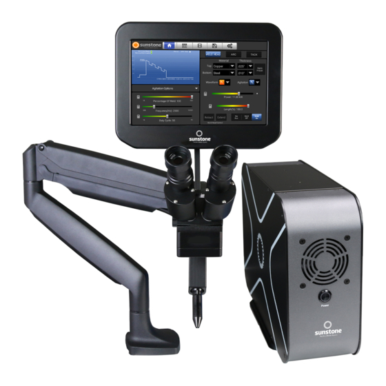
Ω MEGA Chapter 1: Welder Setup & Assembly What is in the Box BOX 1 CONTENTS: (2) Alligator Grounding Clips (1) Sunstone PA250i Series Power Supply (1) Foot Pedal (1) Shielding Gas Hose (2) Power Supply Mounting Brackets (1) Sunstone Touchscreen (1) Electrode Vial (10x 1.0mm Electrodes and 1 Diamond Sharpening Disk) - Page 5 Hardware required from Box 2: Figure 5.1. Attach angled bracket C to A (1) Angled Bracket C (1) Sunstone Microscope Arm Assembly A (1) Clamp Mechanism D (5) Flat Head Hex Screws G • Lay the arm assembly down on the tabletop.
- Page 6 User Manual 250i Ω MEGA Mounting Option 2 - Bolt through Table Mounting Option 2 is best for tables without accessible edg- es. Hardware required from Box 2: (1) Flat Mounting Plate H (3) Flat Head Hex Screws G (1) Long Carriage Bolt F (1) Flat Pressure Plate I (1) Adjustment Knob J Figure 6.1.
-
Page 7: Attach Touchscreen To Microscope Arm
Plug the other end of the Shutter Cable into the shutter port on the back of the Touchscreen. Note: Connecting other RJ45 compatible devices to the Sunstone shutter RJ45 port may damage the welder and/or the other devices. Figure 7.3 After installing the rubber eyepiece covers, use the Shutter Cable to connect the Touchscreen to the bottom of the microscope head. -
Page 8: Welding Stylus
User Manual 250i Ω MEGA Welding Stylus • Remove the Welding Stylus from the accessories box. • Insert the Welding Stylus into the holder at the bottom of the arm assembly as shown in Figure 8.1. • The tubing can be routed up and through the remov- able cable guide portion of the arm if desired. -
Page 9: Electrode Setup
INSTALL THE TUNGSTEN ELECTRODE ONTO THE WELDING STYLUS Figure 9.1. The PA250i is shipped with a 1mm collet and ten (10) electrodes. Also available from Sunstone are See the Stylus Components Chart (Figure 8.4) on previ- 0.5mm electrodes and applicable collet. -
Page 10: Adjusting The Microscope Focus
User Manual 250i Ω MEGA Adjusting The Microscope Focus • Twist the knob on the microscope forward and backward to lower and raise the head. This will allow you to focus the microscope on the welding stylus. See Figure 10.1. •... -
Page 11: Power Supply Setup - Front Panel
Omega PAWH head. • Take the CNC/Sunstone PA250i adapter cable, and plug the green connector into the PLC I/O Port on the PA250i, and the 25 pin parallel connector to the I/O-1 Port (for Janome robotic systems) on the back of the CNC. (The Omega uses a Term Block Plug 20POS STR 3.5mm Part #170182 available from Phoenix Contact.) If you’re using a robotic system from a different... -
Page 12: When To Sharpen The Electrode
Once the electrode is sharp and clean, turn off the rotary tool and insert the electrode back into the stylus as explained above. Note: As a rule of thumb, Sunstone recommends a sharp- ened electrode anytime a new workpiece is being welded. WHEN TO FLATTEN/ BLUNT THE ELECTRODE •... -
Page 13: Shield Gas Setup
e Micro Welder Experts it is recommended to blunt the electrode instead of sharpening it, as shown in Figure 12.3. A flat or blunted electrode is ideal when using the Omega PAWH weld head. • Follow the “When to Sharpen the Electrode” instructions on the previous page. •... -
Page 14: Microscope Lcd Shutter System
>UV 16 and >IR 16 for maximum eye protection. BECOME FAMILIAR WITH THE MICROSCOPE The Sunstone microscope has been designed to provide maximum visual clarity, eye protection, and ease of use. One challenge using the microscope is getting used to bringing the workpiece to the welding electrode while looking through the microscope. -
Page 15: Omega Pawh Weld Head Setup
e Micro Welder Experts Omega PAWH Weld Head Setup These instructions are for the manual version of the Omega PAWH Weld Head. CONNECT THE COMPRESSED AIR • Plug the tube from the compressed air tank into the Air Valve System (A) on the back of the weld head. •... - Page 16 User Manual 250i Ω MEGA into the screw holes, ensuring the weld head will be secured during welding. INSTALL THE WELD HEAD BASE PLATE • Remove the base plate cap. • Now slide the base plate onto the base of the weld head and tighten the wheel on the side of the base plate to secure.
-
Page 17: Chapter 2: User Interface Overview
e Micro Welder Experts Chapter 2: User Interface Overview The PA250i interface consists of five main “screens” that can be accessed at any time using the icons located along the top of the screen in the header area: • Home •... -
Page 18: Waveform Graphic Area
User Manual 250i Ω MEGA Waveform Graphic Area The Waveform Graphic Area (see Figure 18.1) illustrates how energy is released during a weld and provides a quick reference for various settings. The waveform displayed will change based on the control settings you select. (Also see Reading the Waveform Graph on page 43). - Page 19 Micro Welder Experts and then to apply the Sunstone recommended settings. The PA250i will then adjust settings automatically for that application. Settings can be changed if needed. Note: The top material refers to the material that comes into contact with the electrode. For battery welds, as an example, the top material is the tab connecting battery cells, and the bottom material is the battery cell (or can).
- Page 20 Weld State The Sunstone PA250i has three different Weld States: Dry Run, Weld Off, and Weld On. • Weld Off State: In this state, the welder is not ready to make a weld. There is no energy waiting to be released.
- Page 21 The waveform selections determine and control how energy is released when welds are made. • Classic: The Classic waveform is the default waveform for welding on all Sunstone welders. It has a high initial peak current, followed by a capacitive discharge slope. One key advan- tage of the Classic waveform is its ability to create large weld spots with shallow surface penetration, which helps keep the overall workpiece cooler.
- Page 22 User Manual 250i Ω MEGA Agitation During the weld, a high-frequency agitation feature can be used to improve weld formation and strength in certain applications. Positive agitation is added energy to the weld in the form of micro energy bursts. Negative agitation is subtracted energy from the weld in the form of micro energy pockets.
- Page 23 Experimentation with different lengths and power settings can help achieve the best results when using Triangle and Square modes. TACK CONTROL LAYOUT The Sunstone Omega PA250i is capable of performing resistance tack welds. See the Make a Tack Weld sec- tion on page 41 for more information. Figure 23.1. When you touch “TACK”,...
- Page 24 User Manual 250i Ω MEGA • Short: Sets a quarter second delay before initiating the weld. • Medium: Sets a half a second delay before initiating the weld. • Long: Sets a one second delay before initiating the weld. Tack Energy Slider The Tack Energy Slider adjusts the amount of weld energy that is being used.
- Page 25 e Micro Welder Experts Figure 25.1. You are able to customize the information displayed in the Mini-Screen Area. Touch the drop down arrow to view a list of available options. • If you notice that your weld head is frequently misfiring, check your tip shape first, but then you should try adjusting this value down.
-
Page 26: Communication Screen
User Manual 250i Ω MEGA energy adjustments without using hands or looking away from the scope. Touch detect triggering is required when Dynamic Energy Adjustment mode is enabled. • Save Load Mode: Access to saving/loading settings (see the Save/Load Screen section on page 32). •... - Page 27 e Micro Welder Experts tem, if using a PLC. This pinout shows where the various signals would be transmitted from or transmitted to. This diagram also shows locations for a 12V DC signal and a 0V DC signal, useful for reference. Please note that pin 2.7 is not connected internally and does not carry any signal.
- Page 28 The Sunstone PA250i also has a dedicated Weld Trigger input, assigned to pin 1.9. This pin also operates in an active-low configuration, drive this input to 0V to trigger a weld. (if in Arc or Tack mode make sure your trigger method is set to Foot Pedal).
- Page 29 REMOTE SCHEDULE SELECT The Sunstone PA250i contains an advanced Remote Schedule Select Screen (see Figure 29.1), allowing you to assign up to 127 saved welds, and remotely select which one to use. Welds must be saved before they can be assigned on this screen (see the Save/Load Screen section on page 32 for more information on saving welds).
- Page 30 Temperature: This alarm will notify you once the internal temperature crosses your preset temperature threshold. When the alarm is active and enabled, the fans will turn on. Sunstone has also programmed in critical temperature value thresholds, where the fans will turn on regardless of alarm status, and in event of critically high temperatures, welding will be disabled.
-
Page 31: Media Screen
Alarms that are enabled and active will be displayed under the Active Alarms column. Media Screen The Sunstone PA250i has preloaded media that can be viewed from the Media Screen for help and information regarding welding (see Figure 31.1). The Users Manual can also be found here. -
Page 32: Save/Load Screen
Save/Load Screen The Sunstone PA250i can save and load your weld settings for future use. To save your current weld parame- ters, press the Save icon to open the Save/Load Screen (see Figure 32.1). SAVE SETTINGS The parameters will be represented in the graphic waveform window. -
Page 33: Settings Screen
Download Latest Media: Press the Download Latest Media Button (if WiFi is available) to connect to the Sunstone website for the all related media files. If a new file or an updated file exists on the server, it will be downloaded. - Page 34 User Manual 250i Ω MEGA Figure 34.1. Touch the Agitation Button to globally adjust the parameters for agitation. AGITATION OPTIONS Each slider has + and – buttons that will appear for five seconds after the slider has been adjusted. • Agitation Profile Buttons: Press the button for the desired agitation profile (see the Agitation section on page 22).
- Page 35 Micro Welder Experts Figure 35.1. The Sunstone PA250i will digitally display the status of the gas attached to the welder. Touch the Gas Button to calibrate, purge, or adjust other gas-related settings. • Post-Flow Delay Slider: Allows you to set how long the gas will remain on after a weld has taken place.
- Page 36 User Manual 250i Ω MEGA Figure 36.1. Touch the Timing Button to adjust various system timings. Figure 36.2. Touch the Systems Button to restore defaults, update the welder’s software, clear memory, and view revision numbers. 36 • Questions? Call or Text +1-801-658-0015...
- Page 37 Weld Counters: Two weld counters are available. Press the respective Reset Weld Count Buttons to return counter values to zero. LOCK OPTIONS The Sunstone PA250i interface can be Locked to prevent changes to the settings and weld parameters. Refer to Figure 38.1 when referencing the following features: Toggle Lock Mode •...
- Page 38 Depending upon the customer service plan you purchased for your welder, you may be able to receive software and welder setting updates via email. As Sunstone develops new software with more efficient settings and/or features to provide the very best welding experience, these updates will be available on the Sunstone website for download.
- Page 39 e Micro Welder Experts • A popup will appear, informing you that the welder is copying the update file. • A new popup will appear, asking if you would like to install the update. Press Install Button. • A progress bar will show that the update is installing. Close the popup when the installation is complete. •...
-
Page 40: Chapter 3: Make A Weld
Note: A pulse-arc handpiece is used in this mode along with an alligator clip. Ensure the cable has a resistance of at least 20mΩ when using an arc cable not supplied by Sunstone. Do NOT use tack cables for arc welds. For more information on arc welding techniques and specifics, refer to Chapter 4 of the Sunstone Workbook. - Page 41 Ensure the weld cable has a resistance of at least 20mΩ when using an arc cable not supplied by Sunstone. MAKE A TACK WELD For more information on Tack Settings see page 23.
-
Page 42: Finding The Right Settings
To fine tune the results and maximize weld quality, it can be extremely helpful to make use of the many configurations the Sunstone PA250i has to offer. Although it can be intim- idating to experiment with new technology, “playing” with... -
Page 43: Aiming" The Electrode
e Micro Welder Experts TIPS • Try the Classic waveform first as it is usually the easiest to adjust for ideal results. Some metals will weld better using Triangle waveform or Square waveform. Try all three to see the differences. •... -
Page 44: Reading The Waveform Graph
User Manual 250i Ω MEGA Ignition Profiles Ignition: None Ignition: Standard + Ignition: Adaptive Weld Discharge Waveforms Classic Waveform Triangle Waveform Square Waveform Reading the Waveform Graph The waveform graph is a helpful tool for understanding what is taking place during a weld. One quick look can provide information such as which ignition mode is being used, which waveform has been selected, which agitation profile is being used, and the length of the energy discharged. - Page 45 e Micro Welder Experts • Square Mode can also be adjusted independently, but the peak remains constant for the duration of the discharge. This means that twice the energy would be released into the weld site compared to Triangle mode if the peak and lengths were set to the same values. AGITATION PROFILES If agitation is enabled, the spikes will be displayed on the graph accordingly.
-
Page 46: Declaration Of Conformity
Arc Welding Equipment - Safety Requirements The Technical File required by both directives above is maintained at the headquarters of Sunstone Engineering LLC, 1693 American Way Ste 5, Payson Utah 84651 USA. CE Year 2020 46 • Questions? Call or Text +1-801-658-0015... - Page 47 Precise, Repeatable Control Over Every Aspect of Every Weld! The Sunstone hallmark is precision control find the sweet spot for any welding application. over power delivery details. And the Sunstone The CDDP-A is PLC-enabled and automation CDDP-A line of fine-spot resistance welders is ready for any production floor.
- Page 48 1693 American Way Ste 5 • Payson UT 84651 USA Tel. +1-801-658-0015 wwww.sunstonewelders.com PART #1142 ©2022 Sunstone Engineering LLC. Safety information subject to change. Sunstone and Orion are trademarks of Sunstone Engineering LLC. 20220405 •...
Need help?
Do you have a question about the OMEGA PA 250i and is the answer not in the manual?
Questions and answers