Table of Contents
Advertisement
Quick Links
Advertisement
Table of Contents

Related Manuals for SUNSTONE AC1050


Summary of Contents for SUNSTONE AC1050
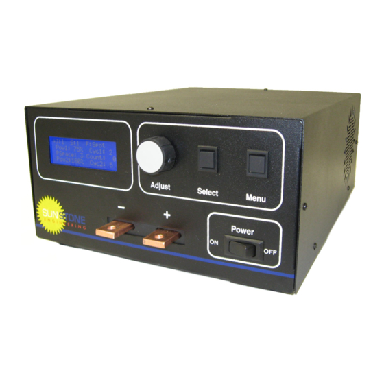
- Page 1 AC1050 User Manual Copyright 2008 Sunstone Engineering R&D Inc.
-
Page 2: Table Of Contents
Contents The AC1050 AC Spot Welder........4 Features................4 Product Data Sheet.............. 5 Safety Procedures and Precautions ........5 Chapter 1: Installation and Setup........6 Positioning Guidelines............6 Foot Switch Setup..............6 Power Cord, Power Source, Fuse, Breaker........7 Cabling Guidelines............... 7 Heat Considerations............. 7 The User Interface............... - Page 3 Appendix D: Warranty and Contact Information..29 Sample Job Documentation Layout......30 NOTE: The information contained in this manual is subject to change as improvements are made to our products. Visit www.SunstoneEngineering.com for the latest version of this document. AC1050 User Manual...
-
Page 4: The Ac1050 Ac Spot Welder
The AC1050 AC Spot Welder The AC1050 AC Spot Welder Features Embedded digital microprocessor with internal memory space for 100 ● user programmable welding schedules. Ability to link multiple schedules together into a job chain. ● Five welding types: ●... -
Page 5: Product Data Sheet
When altering any part of the welding path (such as swapping electrodes ● or cables), turn the unit off or enter the menu to ensure no accidental triggering of a weld. The AC1050 was designed for indoor use only. ● AC1050 User Manual... -
Page 6: Chapter 1: Installation And Setup
See the chapters on each specific weld function for more information (Chapters 2-5). AC1050 User Manual... -
Page 7: Power Cord, Power Source, Fuse, Breaker
Chapter 1: Installation and Setup Power Cord, Power Source, Fuse, Breaker The power cord on the AC1050 can only be connected to 220-240VAC, 50-60Hz electricity. NEVER use a power strip or extension cords with the AC1050. The welder is protected with a 250VAC, 20A time-lag fuse. -
Page 8: The User Interface
6. Main Power Switch: This switch powers the unit. *For more detailed information on the run screen, see the chapter corresponding to the weld function you wish to use (Chapters 2-5). For more information on the menus, see Chapters 6-7. AC1050 User Manual... -
Page 9: Jobs And Schedules
Job 3 . . . Sch 1 Sch 1 Sch 1 Sch 2 Sch 2 Sch 2 Sch 3 Sch 3 Sch 3 Sch 4 Sch 4 Sch 4 ..AC1050 User Manual... -
Page 10: Chapter 2: Spot Weld Function
On the AC1050, the two pulses can be programmed to whatever power level and length is desired and can even be shut off for single pulse operation. -
Page 11: Weld Parameter Definitions
Can be reset to zero by selecting the Reset Schedule Counter option from the main menu. 10. Pulse Two Power: Percentage of maximum power for pulse two. 11. Pulse Two Length: Length in AC cycles for pulse two. AC1050 User Manual... -
Page 12: Example Walkthrough
Adjust Cyc2 to 15 cycles and press Select ● Select Adjust When the workpiece is in position, and the LCD appears as shown, depress ● F:Spot the foot switch to make the weld. Pow1: 50% Cyc1: 5 Pspace: 2 Count: Pow2:100% ►Cyc2:15 AC1050 User Manual... -
Page 13: Chapter 3: Rolling Spot Weld Function
In such an event, an audible alarm will sound. To resume welding, release the foot switch and wait until the internal temperature falls into a normal range. If audible beeps are activated, a short chirp will signal that the unit is ready to weld again. AC1050 User Manual... -
Page 14: Weld Parameter Definitions
Can be reset to zero by selecting the Reset Schedule Counter option from the main menu. 8. Pulse Length: Length in AC cycles for each pulse. 9. Pulse Spacing: Space in AC cycles between subsequent pulses. AC1050 User Manual... -
Page 15: Example Walkthrough
When the workpiece is in position, and the LCD appears as shown, depress ● the foot switch for as long as is desired, then release to end the weld. F:Roll Pow: 75% Count: Cycles On: 15 ►Cycles Off: 30 AC1050 User Manual... -
Page 16: Chapter 4: Seam Weld Function
5. Select Toggle Indicator: 'S' indicates that turning the Adjust Wheel will adjust the currently selected parameter. Nothing indicates that turning the Adjust Wheel will move the cursor. 6. Pulse Power: Percentage of maximum power for pulse. AC1050 User Manual... -
Page 17: Example Walkthrough
Adjust Pow to 85% and then press Select ● Select Adjust When the workpiece is in position, and the LCD appears as shown, depress ● the foot switch for as long as is desired, then release to end the weld. F:Seam ►Pow: 85% Count: AC1050 User Manual... -
Page 18: Chapter 5: Pulsating Spot Weld Function
To initiate the weld, be sure the run screen is displayed and not any of the menu screens. Depress the foot switch and then release to make the weld. If audible beeps are activated, a short chirp will signal that the unit is ready to weld again. AC1050 User Manual... -
Page 19: Weld Parameter Definitions
9. Current Weld Count: Displays the number of welds that have been made with the current job. Can be reset to zero by selecting the Reset Schedule Counter option from the main menu. 10. Pulse Spacing: Spacing in AC cycles between each pulse. AC1050 User Manual... -
Page 20: Example Walkthrough
Select Select Select Adjust Adjust Adjust When the workpiece is in position, and the LCD appears as shown, depress ● the foot switch to make the weld. F:Pulse Pow:100% Cyc: 10 Pulses: 8 Count: ►Cycles Off: 3 AC1050 User Manual... -
Page 21: Chapter 6: Main Menu Functions
Add a Schedule By default, the AC1050 comes with only Schedule 0 activated in all 10 jobs. To use additional schedules they will need to be added by selecting the Add a Schedule function from the main menu. Once selected, a notification will appear displaying the schedule number that was added. -
Page 22: Restart The Schedule Counter
One is attached to the weld transformer and another to the 240VAC switching relay. To view their current readings, select the View Internal Temp option from the Main Menu. To exit press the Menu Button. AC1050 User Manual... -
Page 23: View The Lifetime Weld Counter
Chapter 7: Job Menu Functions and Chaining View the Lifetime Weld Counter The AC1050 keeps track of every weld performed once it leaves the factory. To access this counter select the View Lifetime Welds option from the Main Menu. To exit, press the Menu Button. The lifetime counter provides a convenient way to track the number of daily, monthly, or yearly welds if viewed on a regular basis and recorded. -
Page 24: Remove Last Link From The Chain
While pushing both the Menu Button and the Select Button, turn the unit on. Continue pushing both buttons in for 5 seconds until a warning screen is displayed. After reading the warning, push the Select Button to confirm or the Menu Button to cancel. AC1050 User Manual... -
Page 25: Appendix A: Cable Resistance Chart
To calculate the proper cable lengths from the desired total resistance, use this equation: =l⋅r total internal where : =.062 m ,l=total external cable length , r =cable m per foot internal *NOTE: Exact cable resistances will vary by manufacturer. Use this chart for estimation purposes only. AC1050 User Manual... -
Page 26: Appendix B: Menu Flowcharts
-------------------- Welder Information View Internal Temperature -------------------- Transformer: 27 C Power Relay: 22 C -------------------- View Lifetime Welds -------------------- Lifetime Welds: 10594 -------------------- View Welder Information Sunstone Engineering Model: AC1025 v 1.0 Man Date: Jan 2008 Support:801-658-0015 AC1050 User Manual... -
Page 27: Job Menu
Remove From Chain Remove the Last Link Add a Schedule Change Weld Numbers Lock a Schedule ... -------------------- Last schedule in the chain was removed -------------------- Change the Number of Welds -------------------- Select link to modify: 2 -------------------- AC1050 User Manual... -
Page 28: Appendix C: Glossary
The 240V from electrical outlets is not 240V constantly, but its RMS value is 240VAC RMS. Schedule: On the AC1050, a schedule is the name given to a collection of weld parameters that is part of a job. The Run Screen is always displaying a schedule. -
Page 29: Appendix D: Warranty And Contact Information
90 day warranty period are performed at cost, typically less than $50 USD. Sunstone Engineering offers a 30 day return policy on all of our products. Before sending a product back please contact Sunstone Engineering to receive an RMA number. The RMA number should appear clearly on the outside of the package.
Need help?
Do you have a question about the AC1050 and is the answer not in the manual?
Questions and answers