
Related Manuals for Zebex Z-8182


Summary of Contents for Zebex Z-8182
-
Page 1: Table Of Contents
Z-8182 On-Counter 2D Image Scanner Service Guide Revision History Changes to the original manual are listed below: Version Date Description of Version Feb 26, 2021 Initial release... -
Page 2: Table Of Contents
Table of Contents Table of Contents................................1 Scanner Parts ..................................3 Take Apart ..................................5 Before You Start ..............................5 Important Instructions ..............................5 Tools to Prepare ..................................5... -
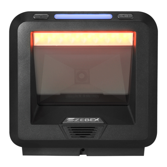
Page 3: Scanner Parts
Scanner Parts The scanner includes the following parts:... - Page 4 Z-8082 Lite 10pin FFC 031-005012-520 Z-6010 12PIN FFC 603-080820-002 Z-8082 front cover rubber 866-818202-703 Z-8182 lens assembly 616-818201-201 Z-8182 Main Board PCBA assembly 605-081820-001 Z-8182 lens rubber 616-818205-201 Z-8182 Switch Board PCBA assembly 689-100000-036 Z-8082 light guide panel 564-080820-005 Z-8082 speaker trigger...
-
Page 5: Take Apart
Read these instructions completely before you begin. Follow all instructions. Heed all warnings. Tools to Prepare Philips screwdriver. Please follow these steps to take apart Z-8182. Slide out the bottom cover (red arrows). Remove the screws and the back cover. - Page 6 Separate the cables and the engine assembly. Remove the front cover rubber. Remove the screws (521-003000-8R0)and separate the trigger rubber, trigger, light guide panel, and switch board.
- Page 7 Remove the screws (M1.8-10.5mm) and remove the 12PIN FFC cable, main board assembly, lens assembly, and lens rubber. Remove the screws M2-5mm(521-013000-5R1) x 6 and M1.6-4mm(521-202000-4R0) x 3. Remove the LED support, LED board, and IO board..
- Page 8 Remove the Lens assembly and the main board.
Need help?
Do you have a question about the Z-8182 and is the answer not in the manual?
Questions and answers