Table of Contents
Advertisement
Advertisement
Table of Contents

Related Manuals for Zebex Z-3052


Summary of Contents for Zebex Z-3052
- Page 2 Copyright © 2007. All rights reserved. No warranty of any kind is made in regard to this material, including, but not limited to, implied warranties of merchantability or fitness for any particular purpose. We are not liable for any errors contained herein nor for incidental or consequential damages in connection with furnishing, performance or use of this material.
-
Page 3: Table Of Contents
Table of Contents Instructions ......................1 1.Getting Started Unpacking ....................2 Scanner Outline ..................3 Disconnecting the cable................4 Connecting to a host ...................4 Assembling of optional stand ..............5 Testing scanning ..................6 What’s on the CD-ROM ................6 Scanner setup.....................7 Operation ....................7 Scanning in handheld mode ...............8 Aiming.......................10 Settings and Programming ............... - Page 4 JPEG quality and size value ............30 Image file format selector ..............31 Bits per pixel ..................31 Signature capture ..................32 Signature capture file format selector ..........33 Signature capture bits per pixel .............33 Signature capture width ..............34 Signature capture height..............34 Signature capture JPEG quality.............34 Video view finder ..................35 Target video frame size..............35 Video view finder image size ............36...
- Page 5 Enable/Disable UPC-E ..............86 Enable/Disable UPC-E1 ..............86 Enable/Disable EAN-8/JAN-8 ............87 Enable/Disable EAN-13/JAN-13 ............87 Enable/Disable Bookland EAN ............87 Decode UPC/EAN/JAN supplemental ...........88 UPC/EAN/JAN supplemental redundancy ........90 Transmit UPC-A check digit ............90 Transmit UPC-E check digit............91 Transmit UPC-E1 check digit............91 UPC-A preamble................92 UPC-E preamble ................93 UPC-E1 preamble .................94 Convert UPC-E to UPC-A..............94 Convert UPC-E1 to UPC-A............95...
- Page 6 Enable/Disable Codabar.............. 118 Set lengths for Codabar............... 118 CLSI Editing.................120 NOTIS Editing................120 MSI ......................121 Enable/Disable MSI ..............121 Set lengths for MSI ..............121 MSI check digits ................123 Transmit MSI check digit(s) ............123 MIS check digit algorithm.............124 Postal Codes...................125 US Postnet ..................125 US Planet ..................125 UK Postal..................126 Transmit UK Postal check digit ............126...
- Page 7 Macro PDF transmit / Decode mode symbols ......144 Transmit Macro PDF control header..........145 Escape characters...............146 Flush Macro buffer...............146 Abort Macro PDF entry..............146 7.Miscellaneous scanner options ................147 Introduction....................147 Miscellaneous scanner parameter defaults ..........148 Miscellaneous scanner parameters ............149 Transmit code ID character ............149 Prefix/Suffix values ..............150 Scan data transmission format ............151 FN1 substitution values ...............152...
-
Page 8: Instructions
Introduction Featuring a powerful image sensor for powerful optical performance, the Handheld 2D Image Reader is ideal for both 1D and 2D scanning situations. The reader uses laser aiming and LED illumination, and LED illumination and can switch between two focus positions for extended working range or for more precise focusing in high-density bar code decoding or digital picture taking With its sturdy ABS plastic construction, sleek, ergonomic styling, and light... -
Page 9: Unpacking
Unpacking The Handheld 2D Image Reader package should contain: 1 ea. Handheld 2D Image Reader 1 ea. Communication Cable 1 ea. Power Adapter (optional) 1 ea. CD-ROM Support Disk If any package contents are damaged or missing, please contact your dealer immediately. -
Page 10: Scanner Outline
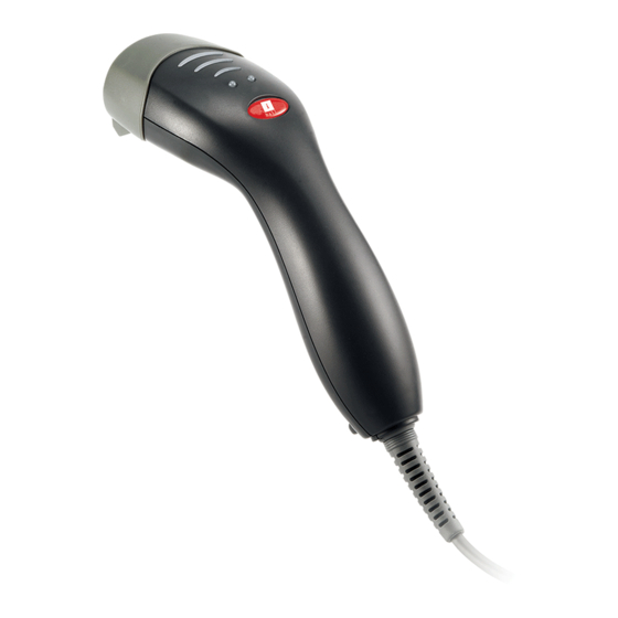
Scanner Outline The LED indicator on the top of the scanner unit glows red when power is on. When a barcode is successfully decoded, the LED flashes green and blue LED and the buzzer sounds. -
Page 11: Disconnecting The Cable
Disconnecting The Cable Prior to removing the cable from the scanner, it is highly advised that the power of the host system is turned off, and power supply disconnected from the cable. 1. Locate the small hole at the bottom of the scanner. 2. -
Page 12: Assembling Of Optional Stand
Assembling the Optional Stand The optional self-supporting stand is to facilitate the usage of your scanner. It moves freely and can be placed anywhere on countertops. It can be tilted to a maximum of 60 degrees. To attach the scanner to the optional stand, hook the scanner on the two holes located at the front of the stand. -
Page 13: Testing Scanning
Test Scanning 1. Ensure all connections are secure, power is connected, and the LED is red, indicating standby position. 2. Aim the scanner at a barcode within range. Assuming the scanner is in trigger mode (default), press the trigger. 3. On successful decode, the scanner beeps and the LED flashes green. 1. -
Page 14: Scanner Setup
Scanner Setup You can configure the scanner either via the Setup utility provided on the CD-ROM, or by scanning the setup codes provided in this manual under Settings and Programming. The setup utility is usually more convenient, but the printed setup codes are supplied for those times when a PC with the necessary utility is not immediately at hand. -
Page 15: Scanning In Handheld Mode
Scanning in Hand-Held Mode Install and program the digital scanner. Scanning with the Scanner 1 Ensure all connections are secure (see the appropriate host chapter.) 2 Aim the digital scanner at the bar code. 3 When the digital scanner senses movement, in its default Auto Aim trigger mode, it projects a red laser aiming pattern (shown as below) which allows positioning the bar code or object within the field of view. - Page 16 5 Hold the trigger until the digital scanner beeps, indicating the bar code is successfully decoded. For more information on beeper and LED definitions. This process usually occurs instantaneously. Steps 2 - 4 are repeated on poor quality or difficult bar codes, until the bar code is decoded, the trigger is released, or the Decode Session Timeout is reached.
-
Page 17: Aiming
Aiming Hold the digital scanner between two and nine inches from the symbol, centering the aiming pattern cross hairs on the symbol. The aiming pattern is smaller when the digital scanner is closer to the symbol and larger when it is farther from the symbol. Scan symbols with smaller bars or elements (mil size) closer to the digital scanner, and those with larger bars or elements (mil size) farther from the digital scanner. -
Page 18: Settings And Programming
Settings and Programming Scan a series of selected barcode patches printed in this manual to affect setup and programming of your Handheld 2D Image Reader. Decoding options and interface protocols can be tailored to a specific application. Setup parameters are stored in non-volatile memory in the scanner and are retained even when power is off. -
Page 19: Set Default Parameter
User Preferences Set Default Parameter Scan this bar code to return all parameters to the default values. Set All Defaults Parameter Scanning To disable decoding of parameter bar codes, scan the Disable Parameter Scanning bar code below. Note that the Set Defaults parameter bar code can still be decoded. -
Page 20: Beeper Volume
Beeper Volume To select a beeper volume, scan the Low Volume, Medium Volume, or High Volume bar code. Low Volume Medium Volume High Volume... -
Page 21: Trigger Modes
Trigger Modes Level - A trigger event activates decode processing, which continues until the trigger event ends, a valid decode, or the decode session time-out is reached. Presentation Mode - When the device detects an object in its field of view it triggers and attempt to decode. The range of object detection does not vary under normal lighting conditions. -
Page 22: Power Modes
Power Mode This parameter determines whether or not power remains on after a decode attempt. In low power mode, the decoder enters into a low power consumption mode to preserve battery life after each decode attempt. In continuous power mode, power remains on after each decode attempt. Continuous On Low Power Mode Time Delay to Low Power Mode... -
Page 23: Decode Session Timeout
1 Minute 5 Minutes 15 Minutes 1 Hour Decode Session Timeout This parameter sets the maximum time decode processing continues during a scan attempt. It is programmable in 0.1 second increments from 0.5 to 9.9 seconds. The default timeout is 9.9 seconds. To set a Decode Session Timeout, scan the bar code below. -
Page 24: Timeout Between Decodes, Same Symbol
Timeout Between Decodes, Same Symbol This option is used in presentation mode to prevent multiple reads of a symbol left in the Device’s field of view. The timeout begins when the symbol is removed from the field of view. It is programmable in 0.1 second increments from 0.0 to 9.9 seconds. -
Page 25: Presentation Mode Session Timeout
Presentation Mode Session Timeout To set the duration of the attempt to decode a bar code detected in presentation mode, scan the bar code below. Next, scan three numeric bar codes from Appendix D, Numeric Bar Codes to select a value between 1 and 255 that represents tenths of a second. - Page 26 Snapshot Aiming Pattern Enable Image Cropping Disable Crop to Pixel Addresses 0 top, 0 left, 479 bottom, 639 right Image Resolution Full JPEG Image Options Quality JPEG Quality Value JPEG Size Value 40 (41K) Image File Format Selection JPEG Bits per Pixel (BPP) 8 BPP Signature Capture Disable...
-
Page 27: Decode Mode
The parameters in this section control image capture characteristics. Image capture occurs in all modes of operation, including decode, video, and snapshot. The decoder has three modes of operation: Decode Mode Snapshot Mode • Snapshot with Viewfinder Mode Video Mode. Decode Mode By default, upon a trigger event, the decoder attempts to locate and decode enabled bar codes within its field of view. -
Page 28: Video Mode
Video Mode In this mode the decoder behaves as a video camera as long as the trigger is active. When the trigger is released, the decoder returns to Decode Mode. Scan this bar code to temporarily enter Video Capture Mode. Video Mode Focus Mode Parameter # F0h, A6h... -
Page 29: Decoding Auto Exposure
Decoding Auto Exposure Select Enable Auto Exposure to allow the device to control gain settings and exposure (integration) time to best capture an image for the selected operation mode. Select Disable Auto Exposure to manually adjust the gain and exposure time. This option is only recommended for advanced users with difficult image capture situations. -
Page 30: Decode Aiming Pattern
Decode Aiming Pattern This parameter only applies when in Decode Mode. Select Enable Decode Aiming Pattern to project the aiming pattern during bar code capture, or Disable Decode Aiming Pattern to turn the aiming pattern off. Enable Decode Aiming Pattern Disable Decode Aiming Pattern Image Capture Auto exposure Select Enable Auto exposure to allow the decoder to control gain settings and... -
Page 31: Image Capture Illumination
Image Capture Illumination Selecting Enable Image Capture Illumination causes the decoder to flash on every image capture. Select Disable Illumination to prevent the decoder from using artificial illumination. Enabling illumination usually results in superior images. The effectiveness of the illumination decreases as the distance to the target increases. Enable Image Capture Illumination Disable Image Capture Illumination Gain... -
Page 32: Exposure Time
Exposure Time This parameter is only available when Image Capture Auto Exposure is disabled. Exposure Time controls the amount of time the CCD is allowed to collect light, much like the shutter speed for a camera. Generally, the brighter the environment, the lower the exposure time. Set the manual exposure time to one of the following values: 5 ms, 10 ms, 15 ms, 20 ms, 25 ms, or 30 ms. -
Page 33: Led Illumination
LED Illumination Parameter # F0h, ADh Select whether to use internal LED illumination, external illumination, or both. This parameter only applies for decoding if Decoding Illumination is enabled, or for image capture if Image Capture Illumination is enabled. If Decoding Illumination or Image Capture Illumination is disabled, all illumination is off for that mode, regardless of this LED Illumination setting. -
Page 34: Snapshot Aiming Pattern
Snapshot Aiming Pattern Select Enable Snapshot Aiming Pattern to project the aiming pattern when in Snapshot Mode, or Disable Snapshot Aiming Pattern to turn the aiming pattern off. Enable Snapshot Aiming Pattern Disable Snapshot Aiming Pattern Image Cropping This parameter crops a captured image. If Disable Image Cropping is selected, the full 640 x 480 pixels are presented. -
Page 35: Crop To Pixel Addresses
Crop to Pixel Addresses If Enable Image Cropping is selected, set the pixel addresses from (0,0) to (639,479) to crop to. Columns are numbered from 0 to 639, rows from 0 to 479. Specify four values for Top, Left, Bottom, and Right, where Top and Bottom correspond to row pixel addresses, and Left and Right correspond to column pixel addresses. -
Page 36: Image Resolution
Image Resolution This option alters image resolution before compression. Multiple pixels are combined to one pixel, resulting in a smaller image containing the original content with reduced resolution. Select one of the following values: Resolution Uncropped Image Value Size Full 640 x 480 320 x 240 212 x 160... -
Page 37: Jpeg Image Options
JPEG Image Options JPEG images can be optimized for either size or for quality. Scan the Quality Selector bar code to enter a quality value; the decoder then selects the corresponding image size. Scan the Size Selector bar code to enter a size value;... -
Page 38: Image File Format Selector
Image File Format Selector Select an image format appropriate for the system (BMP, TIFF, or JPEG). The decoder stores captured images in the selected format. BMP File Format JPEG File Format TIFF File Format Bits per Pixel Select the number of significant bits per pixel (BPP) to use when capturing an image. -
Page 39: Signature Capture
Signature Capture A signature capture bar code is a special-purpose symbology which delineate a signature capture area in a document with a machine-readable format. The recognition pattern is variable so it can optionally provide an index to various signatures. The region inside the bar code pattern is considered the signature capture area. -
Page 40: Signature Capture File Format Selector
Signature Capture File Format Selector Select a signature file format appropriate for the system (BMP, TIFF, or JPEG). The decoder stores captured signatures in the selected format. BMP Signature Format JPEG Signature Format TIFF Signature Format Signature Capture Bits per Pixel Select the number of significant bits per pixel (BPP) to use when capturing a signature. -
Page 41: Signature Capture Width
Signature Capture Width The aspect ratio of the Signature Capture Width and Signature Capture Height parameters must match that of the signature capture area. For example, a 4 x 1 inch signature capture area would require a 4 to 1 aspect ratio of width to height. -
Page 42: Video View Finder
Video View Finder Select Enable Video View Finder to project the video view finder while in Image Mode, or Disable Video View Finder to turn the video view finder off. Disable Video View Finder Enable Video View Finder Target Video Frame Size Select the number of 100-byte blocks to be transmitted per second. -
Page 43: Video View Finder Image Size
Video View Finder Image Size Select the number of 100-byte blocks. Values range from 800 to 3000 bytes. Selecting a smaller value allows more frames to be transmitted per second; selecting a larger value increases video quality. To set the Video View Finder Imager Size, scan the bar code below followed by two bar codes from Appendix D, Numeric Bar Codes corresponding to the 100-byte value from 800 to 3000 bytes. -
Page 44: Serial Interface
Serial Interface Introduction This chapter describes how to set up the decoder with a serial host. The serial interface is used to connect the decoder to point-of sale devices, host computers, or other devices with an available serial port (e.g., com port). If the host is not listed in Table 8-2, refer to the documentation for the host device to set communication parameters to match the host. - Page 45 Serial Host Default Table Parameter Default Serial Host Parameters Serial Host Types Standard Baud Rate 9600 Parity Type None Stop Bit Select 1 Stop Bit Data Bits 8-Bit Check Receive Errors Enable Hardware Handshaking None Software Handshaking None Host Serial Response Time-out 2 Sec RTS Line State Low RTS...
-
Page 46: Serial Host Parameters
Serial Host Parameters Various serial hosts are set up with their own parameter default settings as indicated in table below. Selecting standard, ICL, Fujitsu, Wincor-Nixdorf Mode A, Wincor-Nixdorf Mode B, OPOS/JPOS, Olivetti, or Omron sets the defaults listed below. Terminal Specific Serial Wincor- Wincor- Nixdorf... - Page 47 *In the Nixdorf Mode B, if CTS is Low, scanning is disabled. When CTS is High, the user can scan bar codes. **If Nixdorf Mode B is scanned without the decoder connected to the proper host, it may appear unable to scan. If this happens, scan a different serial host type within 5 seconds of cycling power to the decoder.
- Page 48 Terminal Specific Code ID Characters Wincor- Wincor- Nixdorf Fujitsu Nixdorf Mode B/ Olivetti Omron Mode A OPOS/J UPC-A UPC-E EAN-8/JAN-8 EAN-13/JAN-13 Code 39 None M <len> C <len> <len> Codabar None N <len> N <len> <len> Code 128 None K <len> L <len>...
-
Page 49: Serial Host Types
Serial Host Types To select a serial host interface, scan one of the following bar codes. Enable Serial Host (No Variant) ICL Serial Wincor-Nixdorf Serial Mode A Wincor-Nixdorf Serial Mode B Olivetti ORS4500 Omron *Scanning Enable Serial Host (No Variant) activates the serial driver, but does not change port settings (e.g., parity, data bits, handshaking). -
Page 50: Baud Rate
OPOS/JPOS Fujitsu Serial Baud Rate Baud rate is the number of bits of data transmitted per second. Set the decoder's baud rate to match the baud rate setting of the host device. Otherwise, data may not reach the host device or may reach it in distorted form. - Page 51 Baud Rate 9600 Baud Rate 19,200 Baud Rate 38,400 Baud Rate 57,600 Baud Rate 115,200...
-
Page 52: Parity
Parity A parity check bit is the most significant bit of each ASCII coded character. Select the parity type according to host device requirements. Select Odd parity and the parity bit value is set to 0 or 1, based on data, to ensure that an odd number of 1 bits are contained in the coded character. -
Page 53: Stop Bit Select
Stop Bit Select The stop bit(s) at the end of each transmitted character marks the end of transmission of one character and prepares the receiving device for the next character in the serial data stream. The number of stop bits selected (one or two) depends on the number the receiving terminal is programmed to accommodate. -
Page 54: Check Receive Errors
Check Receive Errors Select whether or not the parity, framing, and overrun of received characters are checked. The parity value of received characters is verified against the parity parameter selected above. Check For Received Errors Do Not Check For Received Errors... -
Page 55: Hardware Handshaking
Hardware Handshaking The data interface consists of a serial port designed to operate either with or without the hardware handshaking lines, Request to Send (RTS), and Clear to Send (CTS). If Standard RTS/CTS handshaking is not selected, scan data is transmitted as it becomes available. - Page 56 decoder issues an error indication and discards the data. RTS/CTS Option 3: When Option 3 is selected, the decoder asserts RTS prior to any data transmission, regardless of the state of CTS. The decoder waits up to Host Serial Response Time-out (default) for CTS to be asserted.
-
Page 57: Software Handshaking
Software Handshaking This parameter offers control of the data transmission process in addition to, or instead of, that offered by hardware handshaking. There are five options. If Software Handshaking and Hardware Handshaking are both enabled, Hardware Handshaking takes precedence. None: When this option is selected, data is transmitted immediately. No response is expected from host. - Page 58 ACK/NAK ACK/NAK with ENQ XON/XOFF...
-
Page 59: Host Serial Response Time-Out
Host Serial Response Time-out This parameter specifies how long the decoder waits for an ACK, NAK, or CTS before determining that a transmission error has occurred. This only applies when in one of the ACK/NAK Software Handshaking modes, or RTS/CTS Hardware Handshaking option. -
Page 60: Rts Line State
RTS Line State This parameter sets the idle state of the Serial Host RTS line. Scan a bar code below to select Low RTS or High RTS line state. Host: Low RTS Host: High RTS Beep on <BEL> When this parameter is enabled, the decoder issues a beep when a <BEL> character is detected on the serial line. -
Page 61: Intercharacter Delay
Inter Character Delay This parameter specifies the intercharacter delay inserted between character transmissions. Minimum: 0 msec Low: 25 msec High: 75 msec Maximum: 99 msec... -
Page 62: Nixdorf Beep/Led Options
Nixdorf Beep/LED Options When Nixdorf Mode B is selected, this indicates when the decoder should beep and turn on its LED after decode. Normal Operation (Beep/LED immediately after decode) Beep/LED After Transmission Beep/LED After CTS Pulse Ignore Unknown Characters Unknown characters are characters the host does not recognize. When Send Bar Codes with Unknown Characters is selected, all bar code data is sent except for unknown characters, and no error beeps sound on the decoder. -
Page 63: Ascii Character Set For Serial Hosts
ASCII Character Set for Serial Hosts The values in the table below can be assigned as prefixes or suffixes for ASCII character data transmission. Prefix/Suffix Values Prefix/Suffix Full ASCII Code 39 ASCII Character Value Encode Character 1000 1001 1002 1003 1004 1005 1006... - Page 64 1022 1023 1024 1025 1026 1027 1028 1029 1030 1031 1032 Space Space 1033 1034 " 1035 1036 1037 1038 & 1039 ‘ 1040 1041 1042 1043 1044 1045 1046 1047 1048 1049 1050...
- Page 65 1051 1052 1053 1054 1055 1056 1057 1058 1059 1060 < 1061 1062 > 1063 1064 1065 1066 1067 1068 1069 1070 1071 1072 1073 1074 1075 1076 1077 1078 1079...
- Page 66 1080 1081 1082 1083 1084 1085 1086 1087 1088 1089 1090 1091 1092 1093 1094 1095 1096 1097 1098 1099 1100 1101 1102 1103 1104 1105 1106 1107 1108...
- Page 67 1109 1110 1111 1112 1113 1114 1115 1116 1117 1118 1119 1120 1121 1122 1123 1124 1125 1126 1127 Undefined 7013 ENTER...
-
Page 68: Usb Interface
USB Interface Introduction This chapter describes how to set up the decoder with a USB host. The decoder connects directly to a USB host, or a powered USB hub, and is powered by it. No additional power supply is required. Throughout the programming barcode menus, default values are indicated with square. -
Page 69: Usb Host Parameters
USB Host Parameters USB Device Type Select the desired USB device type. Note: When changing USB Device Types, the decoder automatically resets. The decoder issues the standard startup beep sequences. HID Keyboard Emulation IBM Table Top USB IBM Hand-Held USB USB OPOS Handheld Simple COM Port Emulation Symbol Native API (SNAPI) with... -
Page 70: Symbol Native Api (Snapi) Status Handshaking
Symbol Native API (SNAPI) Status Handshaking After selecting a SNAPI interface as the USB device type, select whether to enable or disable status handshaking. Enable SNAPI Status Handshaking Disable SNAPI Status Handshaking USB Country Keyboard Types (Country Codes) Scan the bar code corresponding to the keyboard type. This setting applies only to the USB HID Keyboard Emulation device. - Page 71 French Canadian Windows 2000/XP French Canadian Windows 95/98 Spanish Windows Italian Windows Swedish Window UK English Windows Japanese Windows (ASCII) Portuguese-Brazilian Windows...
-
Page 72: Usb Keystroke Delay
USB Keystroke Delay This parameter sets the delay, in milliseconds, between emulated keystrokes. Scan a bar code below to increase the delay when hosts require a slower transmission of data. No Delay Medium Delay (20 msec) Long Delay (40 msec) USB CAPS Lock Override This option applies only to the HID Keyboard Emulation device. -
Page 73: Usb Ignore Unknown Characters
USB Ignore Unknown Characters This option applies only to the HID Keyboard Emulation device and IBM device. Unknown characters are characters the host does not recognize. When Send Bar Codes With Unknown Characters is selected, all bar code data is sent except for unknown characters, and no error beeps sound. -
Page 74: Usb Keyboard Fn 1 Substitution
USB Keyboard FN 1 Substitution This option applies only to the USB HID Keyboard Emulation device. When enabled, this allows replacement of any FN 1 characters in an EAN 128 bar code with a Key Category and value chosen by the user. Enable Disable Function Key Mapping... -
Page 75: Simulated Caps Lock
Simulated Caps Lock When enabled, the decoder inverts upper and lower case characters on the bar code as if the Caps Lock state is enabled on the keyboard. This inversion is done regardless of the current state of the keyboard’s Caps Lock state. Disable Simulated Caps Lock Enable Simulated Caps Lock Convert Case... -
Page 76: Ascii Character Set For Usb
ASCII Character Set for USB USB Prefix/Suffix Values Full ASCII Code Prefix/ Suffix 39 Encode Keystroke Value Character 1000 CTRL 2 1001 CTRL A 1002 CTRL B 1003 CTRL C 1004 CTRL D 1005 CTRL E 1006 CTRL F 1007 CTRL G CTRL 1008... - Page 77 1023 CTRL W 1024 CTRL X 1025 CTRL Y 1026 CTRL Z 1027 CTRL [/ESC1 1028 CTRL \ 1029 CTRL ] 1030 CTRL 6 1031 CTRL 1032 Space Space 1033 1034 “ 1035 1036 1037 1038 & 1039 ‘ 1040 1041 1042 1043...
- Page 78 1052 1053 1054 1055 1056 1057 1058 1059 1060 < 1061 1062 > 1063 1064 1065 1066 1067 1068 1069 1070 1071 1072 1073 1074 1075 1076 1077 1078 1079 1080...
- Page 79 1081 1082 1083 1084 1085 1086 1087 1088 1089 1090 1091 1092 1093 1094 1095 1096 1097 1098 1099 1100 1101 1102 1103 1104 1105 1106 1107 1108 1109...
- Page 80 1110 1111 1112 1113 1114 1115 1116 1117 1118 1119 1120 1121 1122 1123 1124 1125 1126 1The keystroke in bold is sent only if the “Function Key Mapping” is enabled. Otherwise, the unbolded keystroke is sent.
- Page 81 USB ALT Key Character Set ALT Keys Keystroke 2064 ALT 2 2065 ALT A 2066 ALT B 2067 ALT C 2068 ALT D 2069 ALT E 2070 ALT F 2071 ALT G 2072 ALT H 2073 ALT I 2074 ALT J 2075 ALT K 2076...
- Page 82 USB GUI Key Character Set GUI Key Keystroke 3000 Right Control Key 3048 GUI 0 3049 GUI 1 3050 GUI 2 3051 GUI 3 3052 GUI 4 3053 GUI 5 3054 GUI 6 3055 GUI 7 3056 GUI 8 3057 GUI 9 3065 GUI A...
- Page 83 3081 GUI Q 3082 GUI R 3083 GUI S 3084 GUI T 3085 GUI U 3086 GUI V 3087 GUI W 3088 GUI X 3089 GUI Y 3090 GUI Z Note: GUI Shift Keys - The Apple™ iMac keyboard has an apple key on either side of the space bar.
- Page 84 USB F Key Character Set F Keys Keystroke 5001 5002 5003 5004 5005 5006 5007 5008 5009 5010 5011 5012 5013 5014 5015 5016 5017 5018 5019 5020 5021 5022 5023 5024...
- Page 85 USB Numeric Keypad Character Set Numeric Keypad Keystroke 6042 6043 6044 undefined 6045 6046 6047 6048 6049 6050 6051 6052 6053 6054 6055 6056 6057 6058 Enter 6059 Num Lock USB Extended Keypad Character Set Extended Keypad Keystroke 7001 Break 7002 Delete 7003...
- Page 86 7007 Scroll Lock 7008 Backspace 7009 7010 Print Screen 7011 Insert 7012 Home 7013 Enter 7014 Escape 7015 Up Arrow 7016 Down Arrow 7017 Left Arrow 7018 Right Arrow...
-
Page 87: Symbologies
Symbologies Introduction This chapter describes symbology features and provides the programming bar codes for selecting these features. Before programming, follow the instructions in Chapter 1, Getting Started. The device is shipped with the settings shown in the Symbology Default Table If the default values suit requirements, programming is not necessary. -
Page 88: Symbology Parameter Defaults
Symbology Parameter Defaults Table below lists the defaults for all symbologies parameters. To change any option, scan the appropriate barcode(s) provided in the Symbologies Parameters section beginning on 11-10. Note: See Appendix A, Standard Default Parameters for all user preferences, hosts, and miscellaneous default parameters. Symbology Default Table Parameter Default... - Page 89 EAN-8/JAN-8 Extend Disable UCC Coupon Extended Code Disable Code 128 Code 128 Enable UCC/EAN-128 Enable ISBT 128 Enable Code 39 Code 39 Enable Trioptic Code 39 Disable Convert Code 39 to Code 32 (Italian Disable Pharmacy Code) Code 32 Prefix Disable Set Length(s) for Code 39 2 to 55...
- Page 90 Transmit Code 11 Check Digit(s) Disable Interleaved 2 of 5 (ITF) Interleaved 2 of 5 (ITF) Enable Set Lengths for I 2 of 5 I 2 of 5 Check Digit Verification Disable Transmit I 2 of 5 Check Digit Disable Convert I 2 of 5 to EAN 13 Disable Discrete 2 of 5 (DTF)
- Page 91 US Planet Enable UK Postal Enable Transmit UK Postal Check Digit Enable Japan Postal Enable Australian Postal Enable Dutch Postal Enable Transmit US Postal Check Digit Enable RSS (Reduced Space Symbology) RSS 14 Enable RSS Limited Enable RSS Expanded Enable Convert RSS to UPC/EAN Disable Composite...
- Page 92 Code 128 Emulation Disable Data Matrix Enable Maxicode Enable QR Code Enable Symbology-Specific Security Levels Redundancy Level Security Level Intercharacter Gap Size Normal Report Version Macro PDF Macro PDF Transmit/Decode Mode Pass-through Symbols Mode Transmit Macro PDF Control Header Disable Escape Characters None Flush Macro PDF Buffer...
-
Page 93: Upc/Ean
UPC/EAN Enable/Disable UPC-A To enable or disable UPC-A, scan the appropriate barcode below. Enable UPC-A Disable UPC-A Enable/Disable UPC-E To enable or disable UPC-E, scan the appropriate bar code below. Enable UPC-E Disable UPC-E Enable/Disable UPC-E1 UPC-E1 is disabled by default. To enable or disable UPC-E1, scan the appropriate bar code below. -
Page 94: Enable/Disable Ean-8/Jan-8
Enable/Disable EAN-8/JAN-8 To enable or disable EAN-8/JAN-8, scan the appropriate bar code below. Enable EAN-8/JAN-8 Disable EAN-8/JAN-8 Enable/Disable EAN-13/JAN-13 To enable or disable EAN-13/JAN-13, scan the appropriate bar code below. Enable EAN-13/JAN-13 Disable EAN-13/JAN-13 Enable/Disable Bookland EAN To enable/disable Bookland EAN, scan the appropriate barcode below. Enable Bookland EAN Disable Bookland EAN... -
Page 95: Decode Upc/Ean/Jan Supplemental
Decode UPC/EAN/JAN Supplemental Supplemental are bar codes appended according to specific format conventions (e.g., UPC A+2, UPC E+2, EAN 13+2). Six options are available. If Decode UPC/EAN/JAN Only with Supplemental is selected, UPC/EAN/JAN symbols without supplemental are not decoded. If Ignore Supplemental is selected, and the decoder is presented with a UPC/EAN/JAN with a supplemental, the UPC/EAN/JAN is decoded and the supplemental bar code is ignored. - Page 96 Auto discriminate UPC/EAN/JAN Supplemental Enable 378/379 Supplemental Mode Enable 978 Supplemental Mode Enable Smart Supplemental Mode...
-
Page 97: Upc/Ean/Jan Supplemental Redundancy
UPC/EAN/JAN Supplemental Redundancy With Auto discriminate UPC/EAN/JAN Supplemental selected, this option adjusts the number of times a symbol without supplemental is decoded before transmission. The range is from two to thirty times. Five or above is recommended when decoding a mix of UPC/EAN/JAN symbols with and without supplemental, and the auto discriminate option is selected. -
Page 98: Transmit Upc-E Check Digit
Transmit UPC-E Check Digit The check digit is the last character of the symbol used to verify the integrity of the data. Scan the appropriate bar code below to transmit the bar code data with or without the UPC-E check digit. It is always verified to guarantee the integrity of the data. -
Page 99: Upc-A Preamble
UPC-A Preamble Preamble characters are part of the UPC symbol, and include Country Code and System Character. There are three options for transmitting a UPC-A preamble to the host device: transmit System Character only, transmit System Character and Country Code (“0” for USA), and transmit no preamble. Select the appropriate option to match the host system. -
Page 100: Upc-E Preamble
UPC-E Preamble Preamble characters are part of the UPC symbol, and include Country Code and System Character. There are three options for transmitting a UPC-E preamble to the host device: transmit System Character only, transmit System Character and Country Code (“0” for USA), and transmit no preamble. Select the appropriate option to match the host system. -
Page 101: Upc-E1 Preamble
UPC-E1 Preamble Preamble characters are part of the UPC symbol, and include Country Code and System Character. There are three options for transmitting a UPC-E1 preamble to the host device: transmit System Character only, transmit System Character and Country Code (“0” for USA), and transmit no preamble. Select the appropriate option to match the host system. -
Page 102: Convert Upc-E1 To Upc-A
Convert UPC-E1 to UPC-A Enable this to convert UPC-E1 decoded data to UPC-A format before transmission. After conversion, the data follows UPC-A format and is affected by UPC-A programming selections (e.g., Preamble, Check Digit). When disabled, UPC-E1 decoded data is transmitted as UPC-E1 data, without conversion. -
Page 103: Ucc Coupon Extended Code
UCC Coupon Extended Code When enabled, this parameter decodes UPC-A bar codes starting with digit ‘5’, EAN-13 bar codes starting with digit ‘99’, and UPCA/EAN-128 Coupon Codes. UPCA, EAN-13, and EAN-128 must be enabled to scan all types of Coupon Codes. -
Page 104: Code 128
Code 128 Enable/Disable Code 128 To enable or disable Code 128, scan the appropriate bar code below. Enable Code 128 Disable Code 128 Enable/Disable UCC/EAN-128 To enable or disable UCC/EAN-128, scan the appropriate bar code below. Enable UCC/EAN-128 Disable UCC/EAN-128... -
Page 105: Enable/Disable Isbt 128
Enable/Disable ISBT 128 ISBT 128 is a variant of Code 128 used in the blood bank industry. Scan a bar code below to enable or disable ISBT 128. If necessary, the host must perform concatenation of the ISBT data. Enable ISBT 128 Disable ISBT 128... -
Page 106: Code 39
Code 39 Enable/Disable Code 39 To enable or disable Code 39, scan the appropriate bar code below. Enable Code 39 Disable Code 39 Enable/Disable Trioptic Code 39 Trioptic Code 39 is a variant of Code 39 used in the marking of computer tape cartridges. -
Page 107: Convert Code 39 To Code 32
Convert Code 39 to Code 32 Code 32 is a variant of Code 39 used by the Italian pharmaceutical industry. Scan the appropriate bar code below to enable or disable converting Code 39 to Code 32. Note: Code 39 must be enabled for this parameter to function. Enable Convert Code 39 to Code 32 Disable Convert Code 39 to Code 32 Code 32 Prefix... -
Page 108: Set Lengths For Code 39
Set Lengths for Code 39 The length of a code refers to the number of characters (i.e., human readable characters), including check digit(s) the code contains. Set lengths for Code 39 to any length, one or two discrete lengths, or lengths within a specific range. If Code 39 Full ASCII is enabled, Length within a Range or Any Length is the preferred options. -
Page 109: Code 39 Check Digit Verification
Code 39 - Two Discrete Lengths Code 39 - Length Within Range Code 39 - Any Length Code 39 Check Digit Verification When this feature is enabled, the decoder checks the integrity of all Code 39 symbols to verify that the data complies with specified check digit algorithm. Only Code 39 symbols which include a modulo 43 check digit are decoded. -
Page 110: Transmit Code 39 Check Digit
Transmit Code 39 Check Digit Scan a bar code below to transmit Code 39 data with or without the check digit. Transmit Code 39 Check Digit (Enable) Do Not Transmit Code 39 Check Digit (Disable) Note: Code 39 Check Digit Verification must be enabled for this parameter to function. -
Page 111: Code 39 Buffering (Scan & Store)
Code 39 Buffering (Scan & Store) This feature allows the decoder to accumulate data from multiple Code 39 symbols. Selecting the Scan and Store option (Buffer Code 39) temporarily buffers all Code 39 symbols having a leading space as a first character for later transmission. - Page 112 Buffer Data To buffer data, Code 39 buffering must be enabled and a Code 39 symbol must be read with a space immediately following the start pattern. Unless the data overflows the transmission buffer, the decoder issues a lo/hi beep to indicate successful decode and buffering. (For overflow conditions, see Overfilling Transmission Buffer.) The decoder adds the decoded data excluding the leading space to the transmission buffer.
- Page 113 Note: The Transmit Buffer contains only a plus (+) character. In order to scan this command, be sure Code 39 length is set to include length 1. Overfilling Transmission Buffer The Code 39 buffer holds 200 characters. If the symbol just read results in an overflow of the transmission buffer: The decoder indicates that the symbol was rejected by issuing three long, high beeps.
-
Page 114: Code 93
Code 93 Enable/Disable Code 93 To enable or disable Code 93, scan the appropriate bar code below. Enable Code 93 Disable Code 93 Set Lengths for Code 93 The length of a code refers to the number of characters (i.e., human readable characters), including check digit(s) the code contains. - Page 115 Code 93 - One Discrete Length Code 93 - Two Discrete Lengths Code 93 - Length Within Range Code 93 - Any Length...
-
Page 116: Code 11
Code 11 Code 11 To enable or disable Code 11, scan the appropriate bar code below. Enable Code 11 Disable Code 11 Set Lengths for Code 11 The length of a code refers to the number of characters (i.e., human readable characters), including check digit(s) the code contains. -
Page 117: Code 11 Check Digit Verification
Code 11 - One Discrete Length Code 11 - Two Discrete Lengths Code 11 - Length Within Range Code 11 - Any Length Code 11 Check Digit Verification This feature allows the decoder to check the integrity of all Code 11 symbols to verify that the data complies with the specified check digit algorithm. -
Page 118: Transmit Code 11 Check Digits
Two Check Digits Transmit Code 11 Check Digits Parameter # 2Fh This feature selects whether or not to transmit the Code 11 check digit(s). Transmit Code 11 Check Digit(s) (Enable) Do Not Transmit Code 11 Check Digit(s) (Disable) Note: Code 11 Check Digit Verification must be enabled for this parameter to function. -
Page 119: Interleaved 2 Of 5 (Itf)
Interleaved 2 of 5 (ITF) Enable/Disable Interleaved 2 of 5 To enable or disable Interleaved 2 of 5, scan the appropriate bar code below, and select an Interleaved 2 of 5 length from the following pages. Enable Interleaved 2 of 5 Disable Interleaved 2 of 5 Set Lengths for Interleaved 2 of 5 The length of a code refers to the number of characters (i.e., human readable... - Page 120 bar codes in Appendix D, Numeric Bar Codes. For example, to decode I 2 of 5 symbols containing between 4 and 12 characters, first scan I 2 of 5 - Length within Range. Then scan 0, 4, 1, and 2 (single digit numbers must always be preceded by a leading zero).
-
Page 121: I 2 Of 5 Check Digit Verification
I 2 of 5 Check Digit Verification When this feature is enabled, the decoder checks the integrity of all I 2 of 5 symbols to verify the data complies with either the specified Uniform Symbology Specification (USS), or the Optical Product Code Council (OPCC) check digit algorithm. -
Page 122: Convert I 2 Of 5 To Ean-13
Convert I 2 of 5 to EAN-13 Enable this parameter to convert 14-character I 2 of 5 codes to EAN-13, and transmit to the host as EAN-13. To accomplish this, the I 2 of 5 code must be enabled, and the code must have a leading zero and a valid EAN-13 check digit. -
Page 123: Set Lengths For Discrete 2 Of 5
Set Lengths for Discrete 2 of 5 The length of a code refers to the number of characters (i.e., human readable characters), including check digit(s) the code contains. Set lengths for D 2 of 5 to any length, one or two discrete lengths, or lengths within a specific range. One Discrete Length - Select this option to decode only D 2 of 5 symbols containing a selected length. - Page 124 D 2 of 5 – Lengths Within Range D 2 of 5 -Any Length...
-
Page 125: Codabar (Nw-7)
Codabar (NW - 7) Enable/Disable Codabar To enable or disable Codabar, scan the appropriate bar code below. Enable Codabar Disable Codabar Set Lengths for Codabar The length of a code refers to the number of characters (i.e., human readable characters), including check digit(s) the code contains. Set lengths for Codabar to any length, one or two discrete lengths, or lengths within a specific range. - Page 126 scan 0, 2, 1, and then 4. To correct an error or to change the selection, scan Cancel barcode. Length Within Range - Select this option to decode a Codabar symbol with a specific length range. Select lengths using numeric bar codes in Appendix D, Numeric Bar Codes.
-
Page 127: Clsi Editing
CLSI Editing When enabled, this parameter strips the start and stop characters and inserts a space after the first, fifth, and tenth characters of a 14-character Codabar symbol. Enable this feature if the host system requires this data format. Note: Symbol length does not include start and stop characters. Enable CLSI Editing Disable CLSI Editing NOTIS Editing... -
Page 128: Msi
Enable/Disable MSI To enable or disable MSI, scan the appropriate bar code below. Enable MSI Disable MSI Set Lengths for MSI The length of a code refers to the number of characters (i.e., human readable characters), including check digit(s) the code contains. Set lengths for MSI to any length, one or two discrete lengths, or lengths within a specific range. - Page 129 Note: Due to the construction of the MSI symbology, it is possible for a scan line covering only a portion of the code to be interpreted as a complete scan, yielding less data than is encoded in the bar code. To prevent this, select specific lengths (MSI - One Discrete Length - Two Discrete Lengths) for MSI applications.
-
Page 130: Msi Check Digits
MSI Check Digits With MSI symbols, one check digit is mandatory and always verified by the reader. The second check digit is optional. If the MSI codes include two check digits, scan the Two MSI Check Digits bar code to enable verification of the second check digit. -
Page 131: Mis Check Digit Algorithm
MSI Check Digit Algorithm Two algorithms are possible for the verification of the second MSI check digit. Select the bar code below corresponding to the algorithm used to encode the check digit. MOD 10/MOD 11 MOD 10/MOD 10... -
Page 132: Postal Codes
Postal Codes US Postnet To enable or disable US Postnet, scan the appropriate bar code below. Enable US Postnet Disable US Postnet US Planet To enable or disable US Planet, scan the appropriate bar code below. Enable US Planet Disable US Planet... -
Page 133: Uk Postal
UK Postal To enable or disable UK Postal, scan the appropriate bar code below. Enable UK Postal Disable UK Postal Transmit UK Postal Check Digit Select whether to transmit UK Postal data with or without the check digit. Transmit UK Postal Check Digit... -
Page 134: Japan Postal
Japan Postal To enable or disable Japan Postal, scan the appropriate bar code below. Enable Japan Postal Disable Japan Postal Australian Postal To enable or disable Australia Postal, scan the appropriate barcode below. Enable Australian Postal Disable Australian Postal... -
Page 135: Dutch Postal
Dutch Postal To enable or disable Dutch Postal, scan the appropriate bar code below. Enable Dutch Postal Disable Dutch Postal Transmit US Postal Check Digit Select whether to transmit US Postal data with or without the check digit. Transmit US Postal Check Digit Do not Transmit US Postal Check Digit... -
Page 136: Rss (Reduced Space Symbology)
RSS (Reduced Space Symbology) The variants of RSS are RSS 14, RSS Expanded, and RSS Limited. The limited and expanded versions have stacked variants. Scan the appropriate bar code below to enable or disable each variant of RSS. RSS-14 Enable RSS 14 Disable RSS 14 RSS Limited Enable RSS Limited... -
Page 137: Rss Expanded
RSS Expanded Enable RSS Expanded Disable RSS Expanded Convert RSS to UPC/EAN This parameter only applies to RSS-14 and RSS Limited symbols not decoded as part of a Composite symbol. Enable this to strip the leading '010' from RSS-14 and RSS Limited symbols encoding a single zero as the first digit, and report the bar code as EAN-13. -
Page 138: Composite
Composite Composite CC-C Parameter # F0h 55h Scan a bar code below to enable or disable Composite bar codes of type CC-C. Enable CC-C Disable CC-C ) Composite CC-A/B Scan a bar code below to enable or disable Composite bar codes of type CC-A/B. -
Page 139: Composite Tlc-39
Composite TLC-39 Scan a bar code below to enable or disable Composite bar codes of type TLC-39. Enable TLC39 Disable TLC39... -
Page 140: Upc Composite Mode
UPC Composite Mode UPC symbols can be “linked” with a 2D symbol during transmission as if they were one symbol. There are three options for these symbols: Select UPC Never Linked to transmit UPC bar codes regardless of whether a 2D symbol is detected. Select UPC Always Linked to transmit UPC bar codes and the 2D portion. -
Page 141: Composite Beep Mode
Composite Beep Mode To select the number of decode beeps when a composite bar code is decoded, scan the appropriate bar code. Single Beep after both are decoded Beep as each code type is decoded Double Beep after both are decoded... -
Page 142: Ucc/Ean Code 128 Emulation Mode For Ucc/Ean Composite Codes
UCC/EAN Code 128 Emulation Mode for UCC/EAN Composite Codes Select whether to enable or disable this mode. Enable UCC/EAN Code 128 Emulation Mode for UCC/EAN Composite Codes Disable UCC/EAN Code 128 Emulation Mode for UCC/EAN Composite Codes... -
Page 143: 2D Symbologies
2D Symbologies Enable/Disable PDF417 To enable or disable PDF417, scan the appropriate bar code below. Enable PDF417 Disable PDF417 Enable/Disable MicroPDF417 To enable or disable MicroPDF417, scan the appropriate bar code below. Enable MicroPDF417 Disable MicroPDF417... -
Page 144: Code 128 Emulation
Code 128 Emulation When this parameter is enabled, the device transmits data from certain MicroPDF417 symbols as if it was encoded in Code 128 symbols. Transmit AIM Symbology Identifiers must be enabled for this parameter to work. If Code 128 Emulation is enabled, these MicroPDF417 symbols are transmitted with one of the following prefixes: ] C1 if the first codeword is 903-907, 912, 914, 915... -
Page 145: Data Matrix
Data Matrix To enable or disable Data Matrix, scan the appropriate barcode below. Enable Data Matrix Disable Data Matrix Maxicode To enable or disable Maxicode, scan the appropriate bar code below. Enable Maxicode Disable Maxicode QR Code To enable or disable QR Code, scan the appropriate bar code below. Enable QR Code Disable QR Code Redundancy Level... -
Page 146: Redundancy Level
The decoder offers four levels of decode redundancy. Select higher redundancy levels for decreasing levels of bar code quality. As redundancy levels increase, the decoder’s aggressiveness decreases. Select the redundancy level appropriate for the bar code quality. Redundancy Level 1 The following code types must be successfully read twice before being decoded: Code Type... - Page 147 Redundancy Level 1 Redundancy Level 2 Redundancy Level 3 Redundancy Level 4...
-
Page 148: Security Level
Security Level The decoder offers four levels of decode security for delta bar codes, which include the Code 128 family, UPC/EAN, and Code 93. Select increasing levels of security for decreasing levels of bar code quality. There is an inverse relationship between security and decoder aggressiveness, so choose only that level of security necessary for any given application. -
Page 149: Intercharacter Gap Size
Intercharacter Gap Size The Code 39 and Codabar symbologies have an intercharacter gap that is typically quite small. Due to various bar code-printing technologies, this gap can grow larger than the maximum size allowed, preventing the decoder from decoding the symbol. If this problem occurs, scan the Large Intercharacter Gaps parameter to tolerate these out-of-specification bar codes. -
Page 150: Macro Pdf Features
Macro PDF Features Macro PDF is a special feature for concatenating multiple PDF symbols into one file. The decoder can decode symbols that are encoded with this feature, and can store more than 64 kb of decoded data stored in up to 50 Macro PDF symbols. -
Page 151: Macro Pdf Transmit / Decode Mode Symbols
Macro PDF Transmit / Decode Mode Symbols Select one of the options below for handling Macro PDF decoding. In Buffer All Symbols the decoder can handle sets of up to 50 maximum-sized Macro PDF symbols. In all other modes there is no limit to the size of the Macro PDF set. -
Page 152: Transmit Macro Pdf Control Header
Pass-through All Symbols Transmit Macro PDF Control Header When enabled, this activates transmission of the control header, which contains the segment index and the file ID, in Macro PDF symbols. For example, the field may be: \92800000\725\120\343. The five digits after the \928 are the segment index (or block index), and \725\120\343 is the file ID. -
Page 153: Escape Characters
Escape Characters This enables the backslash (\) character as an Escape character for systems that can process transmissions containing special data sequences. Scan a bar code below to either format special data according to the GLI (Global Label Identifier) protocol, or to disable this parameter. This parameter only affects the data portion of a Macro PDF symbol transmission;... -
Page 154: Miscellaneous Scanner Options
Miscellaneous Scanner Options Introduction This chapter includes commonly used bar codes to customize how data is transmitted to the host device. See Appendix A, Standard Default Parameters for all host device and miscellaneous scanner defaults. If the default values suit requirements, programming is not necessary. -
Page 155: Miscellaneous Scanner Parameter Defaults
Miscellaneous Scanner Parameter Defaults Table below lists the defaults for miscellaneous scanner options parameters. To change any option, scan the appropriate barcode(s) provided in the Miscellaneous Scanner Parameter. Note: See Standard Default Parameters for all user preferences, hosts, symbologies, and miscellaneous default parameters. Miscellaneous Scanner Options Default Table Parameter Default... -
Page 156: Miscellaneous Scanner Parameters
Miscellaneous Scanner Parameters Transmit Code ID Character A Code ID character identifies the code type of a scanned bar code. This is useful when the decoder is decoding more than one code type. In addition to any single character prefix already selected, the Code ID character is inserted between the prefix and the decoded symbol. -
Page 157: Prefix/Suffix Values
Prefix/Suffix Values A prefix and/or one or two suffixes can be appended to scan data for use in data editing. To set a value for a prefix or suffix, scan a prefix or suffix bar code below, then scan a four-digit number (i.e., four barcodes from Appendix D, Numeric Bar Codes) that corresponds to that value. -
Page 158: Scan Data Transmission Format
Scan Data Transmission Format To change the scan data format, scan one of the following eight bar codes corresponding to the desired format. If using this parameter do not use ADF rules to set the prefix/suffix. To set values for the prefix and/or suffix, see Prefix/Suffix Values. Data As Is <DATA>... -
Page 159: Fn1 Substitution Values
FN1 Substitution Values The Wedge and USB HID Keyboard hosts support a FN1 Substitution feature. When enabled any FN1 character (0x1b) in an EAN128 bar code is substituted with a value. This value defaults to 7013 (Enter Key). When using host commands to set the FN1 substitution value, set the key category parameter to 1, then set the 3-digit keystroke value. -
Page 160: Maintenance
Maintenance Cleaning the scan window is the only maintenance required. A dirty window may affect scanning accuracy. Never use any abrasive material or solvents on the window. Do not spray water or other cleaning liquids directly onto the window. Remove dirt by wiping gently with a damp cloth or tissue moistened with water and/or ammonia. -
Page 161: Standard Default Parameters
Appendix A Standard Default Parameters Default Parameters Table A-1. Standard Default Parameters Table Parameter Default User Preferences Set Default Parameter All Defaults Parameter Scanning Enable Beeper Tone Medium Beeper Volume High Trigger Modes Level Power Mode Low Power Time Delay to Low Power Mode 1.0 Sec Decode Session Timeout 9.9 Sec... - Page 162 Image Capture Illumination Enable Gain Exposure Time 10 ms Internal LED LED Illumination Illumination 0 (30 Snapshot Mode Timeout seconds) Snapshot Aiming Pattern Enable Image Cropping Disable Crop to Pixel Addresses 0 top, 0 left, 479 bottom, 639 right Image Resolution Full JPEG Image Options Quality...
- Page 163 Target Video Frame Size 2200 bytes Video View Finder Image Size 1700 bytes Event Reporting Decode Event Disable Boot Up Event Disable Parameter Event Disable Serial Host Parameters Serial Host Types Standard Baud Rate 9600 Parity Type None Stop Bit Select 1 Stop Bit Data Bits 8-Bit...
- Page 164 Symbol Native API (SNAPI) Enable Status Handshaking USB Country Keyboard Types North (Country Codes) American USB Keystroke Delay No Delay USB CAPS Lock Override Disable USB Ignore Unknown Enable Characters Emulate Keypad Disable USB FN1 Substitution Disable Function Key Mapping Disable Simulated Caps Lock Disable...
- Page 165 System UPC-E Preamble Character System UPC-E1 Preamble Character Convert UPC-E to A Disable Convert UPC-E1 to A Disable EAN-8/JAN-8 Extend Disable UCC Coupon Extended Code Disable Code 128 Code 128 Enable UCC/EAN-128 Enable ISBT 128 Enable Code 39 Code 39 Enable Trioptic Code 39 Disable...
- Page 166 Code 11 Code 11 Disable Set Lengths for Code 11 4 to 55 Code 11 Check Digit Verification Disable Transmit Code 11 Check Digit(s) Disable Interleaved 2 of 5 (ITF) Interleaved 2 of 5 (ITF) Enable Set Lengths for I 2 of 5 I 2 of 5 Check Digit Verification Disable Transmit I 2 of 5 Check Digit...
- Page 167 Transmit MSI Check Digit Disable Mod 10/Mod MSI Check Digit Algorithm Postal Codes US Postnet Enable US Planet Enable UK Postal Enable Transmit UK Postal Check Digit Enable Japan Postal Enable Australian Postal Enable Dutch Postal Enable Transmit US Postal Check Digit Enable RSS (Reduced Space Symbology)
- Page 168 UCC/EAN Code 128 Emulation Disable Mode for UCC/EAN Composite Codes 2D Symbologies PDF417 Enable MicroPDF417 Disable Code 128 Emulation Disable Data Matrix Enable Maxicode Enable QR Code Enable Symbology-Specific Security Levels Redundancy Level Security Level Intercharacter Gap Size Normal Report Version Macro PDF Macro PDF Transmit/Decode Pass-through...
- Page 169 SSI Suffix 1 Value SSI Suffix 2 <CR> <CR> Value Non-SSI Prefix Value <CR><LF> Non-SSI Suffix 1 Value Non-SSI <CR><LF> Suffix 2 Value <CR><LF> Scan Data Transmission Format Data as is FN1 Substitution Values Transmit “No Read” Message Disable...
-
Page 170: Symbol Code Identifiers
Appendix B Symbol Code Identifiers Symbol Code Characters Code Character Code Type UPC-A, UPC-E, UPC-E1, EAN-8, EAN-13 Code 39, Code 32 Codabar Code 128 Code 93 Interleaved 2 of 5 Discrete 2 of 5, or Discrete 2 of 5 IATA Code 11 UCC/EAN-128 Bookland EAN... -
Page 171: Aim Code Identifiers
US Postnet US Planet Japan Postal UK Postal Dutch Postal Australian Postal UK Postal AIM Code Identifiers Each AIM Code Identifier contains the three-character string ]cm where: ] = Flag Character (ASCII 93) c = Code Character m = Modifier Character Aim Code Characters Code Character Code Type... - Page 172 QR Code Discrete 2 of 5, IATA 2 of 5 Maxicode Bookland EAN, Trioptic Code 39, US Postnet, US Planet, UK Postal, Japan Postal, Australian Postal, Dutch Postal The modifier character is the sum of the applicable option values based on Table B-3.
- Page 173 No check digit processing. Reader has validated check digit. I 2 of 5 Reader has validated and stripped check digit. Example: An I 2 of 5 bar code without check digit, 4123, is transmitted as ]I04123 No check digit processing. Reader has checked check digit.
- Page 174 Check characters validated but not transmitted. No option specified at this time. Always transmit 0. RSS-14 and RSS-Limited transmit with an Application Identifier “01”. Note: In UCC/EAN-128 emulation mode, RSS is transmitted using Code RSS Family 128 rules (i.e., ]C1). Example: An RSS-14 bar code 100123456788902 is transmitted as ]e001100123456788902.
- Page 175 The bar code contains a UCC/EAN-128 symbol, and the first codeword is in the range 908-909. The bar code contains a UCC/EAN-128 symbol, and the first codeword is in the range 910-911. Example: A PDF417 bar code ABCD, with no transmission protocol enabled, is transmitted as ]L2ABCD.
-
Page 176: Sample Barcodes
Appendix C Sample Bar Codes Code 39 123ABC UPC/EAN UPC-A, 100% EAN-13, 100% Code 128 12345678901234567890123456789012345678901234... - Page 177 Interleaved 2 of 5 12345678901231 RSS 14 Note: RSS 14 must be enabled to read the bar code below. 7612341562341 PDF417 Data Matrix Maxicode...
-
Page 178: Numeric Barcodes
Appendix D Numeric Bar Codes For parameters requiring specific numeric values, scan the appropriately numbered bar code(s). - Page 179 Cancel To correct an error or change a selection, scan the bar code below. Cancel...
-
Page 180: Ascii Character Set
Appendix E ASCII Character Set ASCII Value Table Full ASCII Code 39 ASCII Value Keystroke Encode Char 1000 CTRL 2 1001 CTRL A 1002 CTRL B 1003 CTRL C 1004 CTRL D 1005 CTRL E 1006 CTRL F 1007 CTRL G CTRL 1008 H/BACKSPACE1... - Page 181 1018 CTRL R 1019 CTRL S 1020 CTRL T 1021 CTRL U 1022 CTRL V 1023 CTRL W 1024 CTRL X 1025 CTRL Y 1026 CTRL Z 1027 CTRL [ 1028 CTRL \ 1029 CTRL ] 1030 CTRL 6 1031 CTRL 1032 Space...
- Page 182 1041 1042 1043 1044 1045 1046 1047 1048 1049 1050 1051 1052 1053 1054 1055 1056 1057 1058 1059 1060 < 1061 1062 > 1063...
- Page 183 1064 1065 1066 1067 1068 1069 1070 1071 1072 1073 1074 1075 1076 1077 1078 1079 1080 1081 1082 1083 1084 1085 1086...
- Page 184 1087 1088 1089 1090 1091 1092 1093 1094 1095 1096 ‘ 1097 1098 1099 1100 1106 1107 1108 1109...
- Page 185 1110 1111 1112 1113 1114 1115 1116 1117 1118 1119 1120 1121 1122 1123 1124 1125 1126 The keystroke in bold is sent only if the Function Key Mapping is enabled. Otherwise, the unbold keystroke is sent.
- Page 186 ALT Key Standard Default Tables ALT Keys Keystroke 2064 ALT 2 2065 ALT A 2066 ALT B 2067 ALT C 2068 ALT D 2069 ALT E 2070 ALT F 2071 ALT G 2072 ALT H 2073 ALT I 2074 ALT J 2075 ALT K 2076...
- Page 187 USB GUI Key Character Set GUI Key Keystroke 3000 Right Control Key 3048 GUI 0 3049 GUI 1 3050 GUI 2 3051 GUI 3 3052 GUI 4 3053 GUI 5 3054 GUI 6 3055 GUI 7 3056 GUI 8 3057 GUI 9 3065 GUI A...
- Page 188 3081 GUI Q 3082 GUI R 3083 GUI S 3084 GUI T 3085 GUI U 3086 GUI V 3087 GUI W 3088 GUI X 3089 GUI Y 3090 GUI Z Note: GUI Shift Keys - The Apple™ iMac keyboard has an apple key on either side of the space bar.
- Page 189 PF Key Standard Default Table PF Keys Keystroke PF 1 PF 2 PF 3 PF 4 PF 5 PF 6 PF 7 PF 8 PF 9 PF 10 PF 11 PF 12 PF 13 PF 14 PF 15 PF 16...
- Page 190 F key Standard Default Table F Keys Keystroke 5001 5002 5003 5004 5005 5006 5007 5008 5009 5010 F 10 5011 F 11 5012 F 12 5013 F 13 5014 F 14 5015 F 15 5016 F 16 5017 F 17 5018 F 18 5019...
- Page 191 Numeric Key Standard Default Table Numeric Keypad Keystroke 6042 6043 6044 Undefined 6045 6046 6047 6048 6049 6050 6051 6052 6053 6054 6055 6056 6057 6058 Enter 6059 Num Lock...
- Page 192 Extended Keypad Standard Default Table Extended Keypad Keystroke 7001 Break 7002 Delete 7003 Pg Up 7004 7005 Pg Dn 7006 Pause 7007 Scroll Lock 7008 Backspace 7009 7010 Print Screen 7011 Insert 7012 Home 7013 Enter 7014 Escape 7015 Up Arrow 7016 Dn Arrow 7017...
Need help?
Do you have a question about the Z-3052 and is the answer not in the manual?
Questions and answers