Sign In
Upload
Manuals
Brands
ADLINK Technology Manuals
PCI Card
PCIe-U312
ADLINK Technology PCIe-U312 Manuals
Manuals and User Guides for ADLINK Technology PCIe-U312. We have
1
ADLINK Technology PCIe-U312 manual available for free PDF download: User Manual
ADLINK Technology PCIe-U312 User Manual (37 pages)
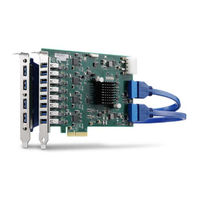
4/8/12-ch PCI Express x4 Gen2 USB3 Vision Top Performing Frame Grabbers
Brand:
ADLINK Technology
| Category:
PCI Card
| Size: 2 MB
Table of Contents
Revision History
2
Preface
3
Table of Contents
5
List of Figures
7
List of Tables
9
Introduction
11
Overview
11
Features
12
Applications
13
Specifications
14
Table 1-1: Pcie-U300 Series Specifications
15
USB Power
16
Overcurrent Protection
16
Software-Programmable USB Power On/Off
16
PCB Layout and Dimensions
17
Pcie-U304 Layout
17
Figure 1-1: Pcie-U304 Top View Dimensions
17
Figure 1-2: Pcie-U304 Side View
17
Figure 1-3: Pcie-U304 Bottom View
18
Figure 1-4: Pcie-U304 Front and Rear View
18
Pcie-U308 Layout
19
Figure 1-5: Pcie-U308 Top View Dimensions
19
Figure 1-6: Pcie-U308 Side View
19
Figure 1-7: Pcie-U308 Bottom View
20
Figure 1-8: Pcie-U308 Front and Rear View
20
Pcie-U312 Layout
21
Figure 1-9: Pcie-U312 Top View Dimensions
21
Figure 1-10: Pcie-U312 Side View
21
Figure 1-11: Pcie-U312 Bottom View
22
Figure 1-12: Pcie-U312 Front and Rear View
22
Board Interfaces
23
Pcie-U304 Interface Layout
23
Figure 2-1: Pcie-U304 Connector, Jumper and LED Locations
23
Table 2-1: Pcie-U304 Connector, Jumper and LED Legend
23
Figure 2-2: Pcie-U304 USB Port Assignment
24
Pcie-U308 Interface Layout
25
Figure 2-3: Pcie-U308 Connector, Jumper and LED Locations
25
Table 2-2: Pcie-U308 Connector, Jumper and LED Legend
25
Figure 2-4: Pcie-U308 USB Port Assignment
26
Pcie-U312 Interface Layout
27
Figure 2-5: Pcie-U312 Connector, Jumper and LED Locations
27
Table 2-3: Pcie-U312 Connector, Jumper and LED Legend
27
Figure 2-6: Pcie-U312 USB Port Assignment
28
Connector, Jumper and LED Definitions
29
USB Ports
29
4-Pin 12V Power Connector (CN10)
29
Figure 2-7: 4-Pin 12V Power Connector
29
Table 2-4: USB 3.0 Type-A Port Pin Assignment
29
Table 2-5: 4-Pin 12V Power Connector Pin Assignment
29
Card ID Switch (SW1)
30
Figure 2-8: Card ID Switch
30
Table 2-6: Card ID Switch Settings
30
Table 2-7: Card ID Switch Legend
30
Status Leds
31
Figure 2-9: Pcie-U300 Series Status Leds
31
Table 2-8: Pcie-U300 Series Status LED Legend
31
Getting Started
33
Unpacking Checklist
33
Installation
33
Important Safety Instructions
35
Getting Service
37
Advertisement
Advertisement
Related Products
ADLINK Technology PCIe-U300 Series
ADLINK Technology PCIe-U304
ADLINK Technology PCIe-U308
ADLINK Technology PCIe-7248
ADLINK Technology PCIe-7296 PCB
ADLINK Technology PCIe-FIW62
ADLINK Technology PCIe-GIE7 Series
ADLINK PCIe-GIE74 PRO
ADLINK Technology PCIe-GIE72 PRO
ADLINK Technology PCIe-8560
ADLINK Technology Categories
Computer Hardware
Motherboard
PCI Card
Control Unit
Desktop
More ADLINK Technology Manuals
Login
Sign In
OR
Sign in with Facebook
Sign in with Google
Upload manual
Upload from disk
Upload from URL