Advertisement
Quick Links
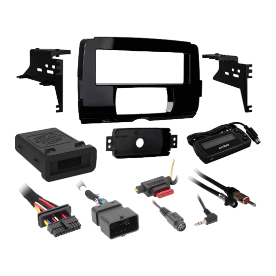
KIT COMPONENTS
• A) Radio housing • B) Radio brackets • C) LCD screen • D) LCD back plate • E) #8 x 3/8" Phillips screws (6) • F) #10-32 1/2" Phillips steel machine screws (4)
A
B
The World's best kits.
®
Harley-Davidson Street Glide, Electra Glide,
Ultra, and Limited Models 2014-Up†
Road Glide 2015-Up†
†
Non-amplified models only
Visit MetraOnline.com for more detailed information about the product and up-to-date vehicle
specific applications
KIT FEATURES
• ISO DIN radio provision
• Saddle Tramp interface with built in handlebar controls
• Water resistant enclosure for added protection
• Antenna adapter included
C
E
MetraOnline.com
D
F
© COPYRIGHT 2021 METRA ELECTRONICS CORPORATION
BC-HDR-K3
I N S TA L L AT I O N I N S T R U C T I O N S
TABLE OF CONTENTS
Fairing Disassembly
Harley Davidson Street Glide, Electra Glide,
Ultra, and Limited models 2014-up .............2-3
Harley Davidson Road Glide 2015-up..............4
Kit Assembly ..........................................................5
Saddle Tramp Interface Installation . ...............6-10
WIRING & ANTENNA CONNECTIONS (Included)
Wiring Harness: Saddle Tramp interface and
harness
Antenna Adapter
Handlebar Control interface
TOOLS REQUIRED FOR KIT INSTALLATION
• Panel removal tool • Phillips screwdriver
• Torx screwdrivers • Allen wrenches
ATTENTION: With the key out of the ignition,
disconnect the negative battery terminal
before installing this product. Ensure that all
installation connections are secure before
cycling the ignition to test this product.
NOTE: Refer also to the instructions included
with the aftermarket radio.
REV. 12/2/21 INSTBC-HDR-K3
Advertisement

Related Manuals for Metra Electronics Saddle Tramp BC-HDR-K3


Summary of Contents for Metra Electronics Saddle Tramp BC-HDR-K3
- Page 1 BC-HDR-K3 I N S TA L L AT I O N I N S T R U C T I O N S Harley-Davidson Street Glide, Electra Glide, TABLE OF CONTENTS Fairing Disassembly Ultra, and Limited Models 2014-Up† Harley Davidson Street Glide, Electra Glide, Road Glide 2015-Up† Ultra, and Limited models 2014-up .....2-3 Harley Davidson Road Glide 2015-up....4 †...
- Page 2 FAIRING DISASSEMBLY Harley Davidson Street Glide, Electra Glide, Ultra, and Limited models 2014-up 1. Remove (4) T-27 Torx screws from the inner fairing. (Figure A) 2. With a firm grip on the windshield, remove (3) T-27 Torx screws, and then remove the windshield. (Figure B) Note: The outer fairing will also be loosened. 3. Remove the outer fairing, unplugging (Figure A) (Figure C) the headlight. (Figure C) 4. Remove (2) T-27 Torx screws to remove the fairing vent, and then remove the vent. (Figure D Continued on next page (Figure B) (Figure D) 386.257.1187...
- Page 3 FAIRING DISASSEMBLY (CONT) 5. Remove (11) screws securing the radio“dummy” bracket: (Figure E) a. (2) T-27 Torx screws shared with the gauge cluster and a third T-27 Torx screw to remove the gauge cluster in step 7. b. (4) 5/32" Allen screws facing outward. c. (4) T-25 Torx screws secured to the radio “dummy”. d. (1) T-25 Torx screw shared with the storage pocket. 6. Remove the radio bracket. (Figure E) Note: This bracket will be reused with the kit assembly. (Figure E) 7. Remove the gauge cluster. (Figure E) 8. Remove (4) 3/16" Allen screws from the sides of radio. (Figure F) Note: These screws will be reused with the kit assembly. 9. Slide the radio out toward the rear of (Figure F) the bike, disconnect the wiring, and then remove the radio. (Figure F) Continue to Kit Assembly REV.
- Page 4 FAIRING DISASSEMBLY (CONT) Harley Davidson Road Glide 2015-up 6. Remove the speaker grills with a panel removal tool and remove (1) Torx screw 1. Remove the lower torx screws on either from each side. (Figure E) side holding the wind deflector wings. CAUTION: The fairing will be loose at this (Figure A) point. Have a helper hold it to keep from Note: Only the lower two need to be damaging it when removing the screws. removed. 7. Remove the fairing and set aside. (Figure A) (Figure D) 2. Remove (1) 3/16" Allen screw from each of the turn signals. (Figure B) 8. Remove (4) 3/16" Allen screws from the sides of the factory radio. 3. Remove (4) Phillips screws from the Note: These screws will be reused in the windshield and set the windshield BC-HDR-K3 kit assembly. aside. (Figure C) CAUTION: Be sure to hold the radio 4. Remove the top fairing trim clipped to...
- Page 5 KIT ASSEMBLY 1. Secure the radio brackets to the radio housing with (4) #8 x 3/8" Phillips screws provided in this kit. (Figure A) 2. Slide the aftermarket radio into the radio housing assembly and secure with screws supplied with the radio. (Figure B) 3. Secure the radio housing assembly to the bike using (4) 3/16" Allen screws previously removed in step 8 of disassembly. (Figure C) (Figure A) (Figure B) (Figure C) Continue to BC-HDR-K3 Interface Installation REV. 12/2/21 INSTBC-HDR-K3...
-
Page 6: Table Of Contents
SADDLE TRAMP INTERFACE INSTALLATION INTERFACE FEATURES TABLE OF CONTENTS • Provides accessory power (12-volt 10-amp) Installation ..............................6 • Retains balance Connections ...............................7 • Retains handlebar controls Programming ............................8 • H-D Handlebar controls can be added LCD Operation ............................9 • 71500248C ‘14-’20 w/o Traction Control Troubleshooting ............................10 • 71500561 ‘20-Up w/Traction Control • USB Micro-B updatable INTERFACE COMPONENTS TOOLS REQUIRED TO MAKE ELECTRICAL CONNECTIONS • Saddle Tramp Interface: • Cutting tool • Crimping tool • Tape • Circuit board... -
Page 7: Connections
CONNECTIONS Fuse Front Rear View AUX-IN Rear Inside Case Yellow - Battery power Black - Ground Red - Accessory power Orange - Illumination Blue - Power antenna Gray - Front right speaker (+) Gray/Black - Front right speaker (-) White - Front left speaker (+) Vehicles without handlebar controls White/Black - Front left speaker (-) 1. -
Page 8: Programming
PROGRAMMING 1. Turn the ignition on. 5. The LED light will flash Green & Red while the interface programs the radio to the handlebar controls. Once programmed, the LED light will go out, then produce a pattern which will identify the radio type installed. Green & Red LED 2. Connect the BC-HDR-K3 harness to the wiring harness in the bike. Green or Red LED 6. The LED light will go out, then once again quickly flash Green & Red while the interface programs itself to the vehicle. Once programmed, the LED light will go out again, then turn solid Green. Green & Red LED 3. For vehicles without hand controls: The interface will automatically program. Do Not Touch Green LED 7. Turn the ignition off, then back on. 4. -
Page 9: Lcd Operation
LCD OPERATION The included LCD screen provides oil pressure and EITMS status. For more information, IMPORTANT NOTE please see the owner’s manual that came with the bike. Main menu options: If the Oil/EITMS information does not show up on the kit, perform this step; • Red adjusts the red backlighting of the LCD (ranges from 1 to 32). • Press and hold the “Return/ESC” button on the LCD screen for 5 seconds until “Select Interface” comes up. • Blue adjusts the blue backlighting of the LCD (ranges from 1 to 32). -
Page 10: Troubleshooting
TROUBLESHOOTING Final LED Feedback If the interface fails to function you will At the end of programming the LED light will turn Solid Green which indicates programming need to press the reset button. To access Reset Button was successful. If the LED light didn’t turn Solid Green, reference the list below to understand the button remove the cover of the water which programming section the problem may stem from. resistant case, slide out the circuit board and press the reset button. The LED will start flashing, starting at step 2, repeat the Radio Vehicle Programming LED Light programing process. Programming Section Section Solid Green Pass Pass LED Light Slow Red Flash Fail Pass Slow Green Flash Pass Fail Solid Red Fail Fail Note: If the LED light shows Solid Green for Pass (indicating everything programmed correctly), yet the steering wheel controls don’t work, check to ensure that the 3.5mm jack is plugged in, and also plugged into the correct jack on the radio. Once corrected, press the reset button, then program again. - Page 11 REV. 12/2/21 INSTBC-HDR-K3...
- Page 12 BC-HDR-K3 I N S TA L L AT I O N I N S T R U C T I O N S Having difficulties? We’re here to help. Contact our Tech Support line at: 386-257-1187 Or via email at: techsupport@metra-autosound.com Tech Support Hours (Eastern Standard Time) Monday - Friday: 9:00 AM - 7:00 PM Saturday: 10:00 AM - 7:00 PM Sunday: 10:00 AM - 4:00 PM ® NOWLEDGE IS OWER Enhance your installation and fabrication skills by enrolling in the most recognized and respected...
Need help?
Do you have a question about the Saddle Tramp BC-HDR-K3 and is the answer not in the manual?
Questions and answers