Advertisement
Quick Links
INSTALLATION INSTRUCTIONS FOR PART 95-7801
APPLICATIONS
See Application List Inside
95-7801
KIT FEATURES
• Double DIN Radio Provision
• Stacked ISO Units Provision
KIT COMPONENTS
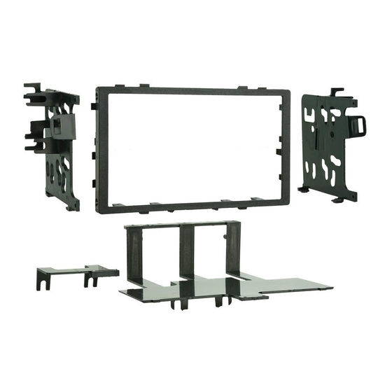
• A) Radio Housing • B) Rear Support Tray • C) ISO Brackets
• D) Mounting Bracket (Acura legend) • E) (2) #8 x 1/2" Phillips Pan Head Screws
• F) (6) #6 x 1/4" Phillips Flat Head Screws
B
A
C
D
E
F
TOOLS REQUIRED:
• Phillips Screwdriver • Cutting Tool
1-800-221-0932
www.metraonline.com
© COPYRIGHT 2001-2008 METRA ELECTRONICS CORPORATION
Advertisement

Summary of Contents for Metra Electronics 95-7801
- Page 1 INSTALLATION INSTRUCTIONS FOR PART 95-7801 APPLICATIONS See Application List Inside 95-7801 KIT FEATURES • Double DIN Radio Provision • Stacked ISO Units Provision KIT COMPONENTS • A) Radio Housing • B) Rear Support Tray • C) ISO Brackets • D) Mounting Bracket (Acura legend) • E) (2) #8 x 1/2” Phillips Pan Head Screws •...
- Page 2 95-7801 T ABLE OF CONTENTS Dash Disassembly / Kit Preparation - ACURA - CL 1997-99 ......... . 1 - Integra 1990-93 .
- Page 3 Rear Support Tray (Fig. A). Cut and remove all mounting clips on the Radio Housing EXCEPT clips "C" and "H" (Fig. B). Skip to step #3b on Page 10. 95-7801 DASH DISASSEMBL Y "A" "A" "H" "H"...
- Page 4 3 Attach the Mounting Bracket to the bottom of the Rear Support Tray (Fig. A). Cut and remove all mounting clips on the Radio Housing EXCEPT clips "E" and "J". (Fig. B) Skip to step #3b on Page 10. 95-7801 DASH DISASSEMBL Y "E" "C" Fig. A "C"...
- Page 5 Rear Support Tray (Fig. A). Cut and remove all mounting clips on the Radio Housing EXCEPT clips "A" and "H" (Fig. B). Skip to step #3b on Page 10. 95-7801 DASH DISASSEMBL Y Fig. A "B" Fig. B "B"...
- Page 6 (Fig. A) 3 Cut and remove all mounting clips on the Radio Housing EXCEPT clips "A" and "H". (Fig. B) Skip to step #3b on Page 10. 95-7801 DASH DISASSEMBL Y "C" Fig. A "C" "H"...
- Page 7 (Fig. A) 3 Cut and remove all mounting clips on the Radio Housing EXCEPT clips "B" and "H". (Fig. B) Skip to step #3a on Page 9. 95-7801 DASH DISASSEMBL Y Fig. A Fig. B "A"...
- Page 8 (Fig. A) Cut and remove all mounting clips on the Radio Housing EXCEPT clips "C" and "H". Skip to step #3a on Page 9. 95-7801 DASH DISASSEMBL Y (Fig. B) "B" Fig. A "B"...
- Page 9 "B" on the ISO Brackets for mounting, cut and remove tabs "A" (Fig. C). Cut and remove all mounting clips on the Radio Housing. (Fig. B) Skip to step #3b on Page 10. 95-7801 DASH DISASSEMBL Y ISUZU OASIS 1996-1999 Fig. A "D" "H"...
- Page 10 (Fig. A) Cut and remove all mounting clips on the Radio Housing EXCEPT clips "A" and "G". (Fig. B) Skip to step #3a on Page 9. 95-7801 DASH DISASSEMBL Y Fig. B "F" "H" Fig. C "F"...
- Page 11 Align the holes in the brackets with the holes in the units and secure with the screws included with the units. Snap the Radio Housing into the radio open- ing (Fig. F). Skip to step #4 on Page 11. 95-7801 KIT PREPARATION...
- Page 12 Snap the head unit/kit assembly into the sub- dash. ACCORD 1998-02, ODYSSEY 1999-02: Mount the head unit/kit assembly to the sub- dash with (4) screws previously removed in step #1. ( Skip to Final Assembly on page 11.) 95-7801 KIT ASSEMBL Y...
-
Page 13: Final Assembly
Dimmer ....Orange / White *NOTE: When a Black wire is not present, ground radio to vehicle chassis. All colors may not be present on all leads due to manufacturer’s specifications. 95-7801 FINAL ASSEMBL Y Step 4. (A) Strip wire ends back 1/2"... - Page 14 95-7801 NOTES...
- Page 15 95-7801 NOTES...
- Page 16 95-7801 INSTRUCTIONS www.metraonline.com 1-800-221-0932 REV. 04/21/08 © COPYRIGHT 2001-2008 METRA ELECTRONICS CORPORATION INST95-7801...


Need help?
Do you have a question about the 95-7801 and is the answer not in the manual?
Questions and answers