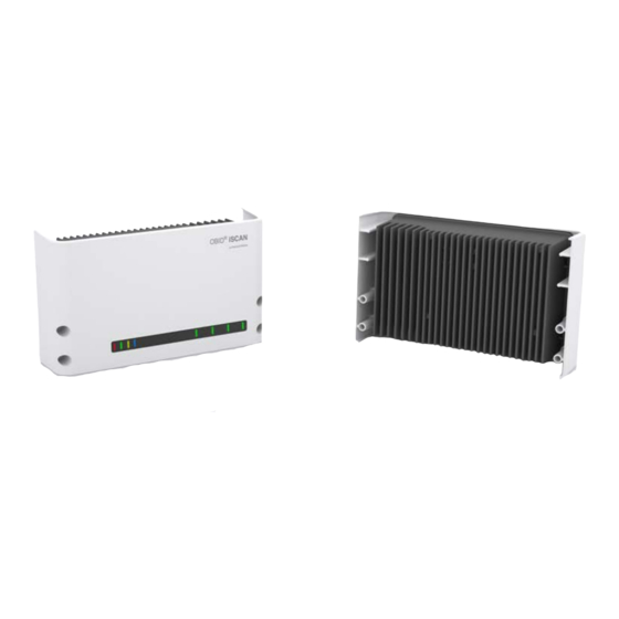
Feig Electronic OBID ID ISC.LRU3000 Manual
Uhf long range reader
Hide thumbs
Also See for OBID ID ISC.LRU3000:
- Installation instructions manual (30 pages) ,
- Installation manual (32 pages)

Related Manuals for Feig Electronic OBID ID ISC.LRU3000


Summary of Contents for Feig Electronic OBID ID ISC.LRU3000
- Page 1 MANUAL ID ISC.LRU3000 / ID ISC.LRU3500 UHF Long Range Reader Firmware-Versions RFC: ≥ 02.08.00 ACC: ≥ 02.06.00 final – public (B) 2012-11-07 – H90202-7e-ID-B.docx...
- Page 2 FEIG ELECTRONIC call explicit attention that devices which are subject of this document are not designed with components and testing methods for a level of reliability suitable for use in or in connection with surgical implants or as critical components in any life support systems whose failure to perform can reasonably be expected to cause significant injury to a human.
- Page 3 • The following figure formats are used: 0...9: for decimal figures 0x00...0xFF: for hexadecimal figures, b0...1 for binary figures. • The hexadecimal value in brackets "[ ]" marks a control byte (command). FEIG ELECTRONIC GmbH Page 3 of 193 H90202-7e-ID-B.docx...
- Page 4 7.2. CFG1: Interface and Mode ....................26 7.2.1. Magnetic Strip Emulation ................... 32 7.2.2. Wiegand Emulation ....................33 7.3. CFG2: Inputs / Outputs ....................35 7.3.1. Dedicated Input / Output Functions ................37 7.4. CFG3: RF-Interface ......................38 FEIG ELECTRONIC GmbH Page 4 of 193 H90202-7e-ID-B.docx...
- Page 5 7.26. CFG71: WLAN Settings, Part 2 ..................89 7.27. CFG72: WLAN Settings, Part 3 ..................90 7.28. CFG73 : WLAN Settings, Part 4 ..................91 7.29. CFG74: WLAN Security Settings, Part 1 ..............93 FEIG ELECTRONIC GmbH Page 5 of 193 H90202-7e-ID-B.docx...
- Page 6 9.2. [0x63] RF Controller Reset .................... 121 9.3. [0x64] System Reset ...................... 122 9.4. [0x66] Get Reader Info....................123 9.5. [0x69] RF Reset......................134 9.6. [0x6A] RF Output ON/OFF ..................... 135 9.7. [0x6E] Reader Diagnostic ..................... 137 FEIG ELECTRONIC GmbH Page 6 of 193 H90202-7e-ID-B.docx...
- Page 7 11.4. [0x22] Read Buffer ...................... 177 11.5. [0x31] Read Data Buffer Info ..................182 11.6. [0x32] Clear Data Buffer ....................183 11.7. [0x33] Initialize Buffer ....................184 11.8. [0x34] Force Notify Trigger ..................185 FEIG ELECTRONIC GmbH Page 7 of 193 H90202-7e-ID-B.docx...
- Page 8 ANNEX C: Index of Status Bytes ..................188 ANNEX D: Discontinued Protocols for Reader Configuration........... 191 ANNEX D1: [0x80] Read Configuration ................191 ANNEX D2: [0x81] Write Configuration ................192 ANNEX D3: [0x83] Set Default Configuration ..............193 FEIG ELECTRONIC GmbH Page 8 of 193 H90202-7e-ID-B.docx...
- Page 9 Although this device doesn't exceed the valid limits for electromagnetic fields you should keep a minimum distance of 25 cm between the device and your cardiac pacemaker and not stay in an immediate proximity of the device respective the antenna for some time. FEIG ELECTRONIC GmbH Page 9 of 193 H90202-7e-ID-B.docx...
- Page 10 [0x6E] Reader Diagnostic, new Mode 0x21 [0x23] Read Multiple Blocks, Read Complete Bank in dependency of DB-ADR [0x24] Write Multiple Blocks, Bytes added in case of error code [0x18] Kill, Recommissioning Bits added FEIG ELECTRONIC GmbH Page 10 of 193 H90202-7e-ID-B.docx...
- Page 11 Most Significant Byte Number Output Read / Write Access Read Relay Radio Frequency RSSI Received Signal Strength Indicator Real Time Clock Table Transponder Timeslot Unique Identifier (read only Serial Number) Write Only Access Write FEIG ELECTRONIC GmbH Page 11 of 193 H90202-7e-ID-B.docx...
- Page 12 All ports are under control of the ACC. Furthermore, the reader has digital I/O’s for direct control of various trigger possibilities and various outputs for a direct control of several indicators. FEIG ELECTRONIC GmbH Page 12 of 193 H90202-7e-ID-B.docx...
- Page 13 Host (Terminal / PC / ..) Reader → parameter- / control command parameter received and stored / control command processed ← status / error status data ← FEIG ELECTRONIC GmbH Page 13 of 193 H90202-7e-ID-B.docx...
- Page 14 Transponder read Transponder data in Reader field ← → write data to Transponder with UID Transponder with correct UID in antenna field? ← OK status status Transponder in Reader field ← FEIG ELECTRONIC GmbH Page 14 of 193 H90202-7e-ID-B.docx...
- Page 15 = no valid data protocol data ← → clear data Transponder data read? ← OK status status = no valid data ← NOTE: Only read operations are available with the Buffered Read Mode. FEIG ELECTRONIC GmbH Page 15 of 193 H90202-7e-ID-B.docx...
- Page 16 Independent of Read Trigger Input/Status and Data Events are notified together in one message. The notifica- tion is activated by command [0x34] Force Notify Trigger. The message format depends on settings in TR-DATA of CFG11. FEIG ELECTRONIC GmbH Page 16 of 193 H90202-7e-ID-B.docx...
- Page 17 Keepalive messages are always never acknowledged by the host. The Keepalive message should not be mistaken with the keepalive option (s. CFG69 ff.) of a LAN/WLAN connection initiated by a host. FEIG ELECTRONIC GmbH Page 17 of 193 H90202-7e-ID-B.docx...
- Page 18 During data transfer via the asynchronous interface the Reader supplies the required data or a status byte. The reply contains the transmitted control byte. There is no reply from the Reader if there is a protocol frame failure. FEIG ELECTRONIC GmbH Page 18 of 193 H90202-7e-ID-B.docx...
- Page 19 The Reader will always response with ad- vanced protocol frame. see ANNEX C: Index of Status Bytes see ANNEX C: Index of Status Bytes FEIG ELECTRONIC GmbH Page 19 of 193 H90202-7e-ID-B.docx...
- Page 20 The data will be sent always as MSB first if the Reader is in the Host Command Mode. CRC16: Cyclic redundancy check of the protocol bytes from 1 to n-2, as specified by CCITT-CRC16 Polynomial: + 1 (0x8408) Start Value: 0xFFFF Direction: Backward FEIG ELECTRONIC GmbH Page 20 of 193 H90202-7e-ID-B.docx...
- Page 21 /* cnt = number of protocol bytes without CRC */ crc ^= DATA[i]; for (j = 0; j < 8; j++) if (crc & 0x0001) crc = (crc >> 1) ^ CRC_POLYNOM; else crc = (crc >> 1); FEIG ELECTRONIC GmbH Page 21 of 193 H90202-7e-ID-B.docx...
- Page 22 Reader. If a checksum error is found, the Reader goes into an error status "EE-Init-Mode" and sets the configuration block which is faulty to the default-values. FEIG ELECTRONIC GmbH Page 22 of 193 H90202-7e-ID-B.docx...
- Page 23 Reader. after writing / saving this configuration block EEPROM and a reset of the RF Controller with 9.3. [0x64] System Reset in mode 0x00. FEIG ELECTRONIC GmbH Page 23 of 193 H90202-7e-ID-B.docx...
- Page 24 The Bit in CFG_NO defines if the access to the configuration block is free or if the use should login to the Reader to get access to the configuration block. b0 ⇒ Access if free b1 ⇒ Access need a login FEIG ELECTRONIC GmbH Page 24 of 193 H90202-7e-ID-B.docx...
- Page 25 It is possible to disable the READER-ID with an activation code, if the READER-ID is un- known. The activation code must be ordered by your supplier or FEIG ELECTRONIC GmbH. Config Protection By means of Config Protection, the access to the configuration parameters stored within the Read- er is protected by a 32-bit password, the "READER-ID".
- Page 26 38400 baud 0x09: 57600 baud 0x0A: 115200 baud A reasonableness check is performed by writing this parameter to the Reader. If an error occurs the Read- er answers with STATUS = 0x11. FEIG ELECTRONIC GmbH Page 26 of 193 H90202-7e-ID-B.docx...
- Page 27 Always 8 Data Bits and 1 Stop Bits should be used. A reasonableness check is performed by writing this parameter to the Reader. If an error occurs the Read- er answers with STATUS = 0x11. FEIG ELECTRONIC GmbH Page 27 of 193 H90202-7e-ID-B.docx...
- Page 28 Selection of the communication port for Scan-Mode Function DC-Format IF-NO IF-NO: Interface Number b000: RS232 b001: RS485 b010: - do not use – b011: Data clock b1xx: - do not use – FEIG ELECTRONIC GmbH Page 28 of 193 H90202-7e-ID-B.docx...
- Page 29 Wiegand emulation (see 7.2.2. Wiegand Emulation) data format: Wiegand formatted protocol frame INTERFACES: (HostInterface.Interfaces) Flags for enabling the communication ports Function Discovery WLAN RS4xx RS232 RS232: b0: disable b1: enable RS485: b0: disable b1: enable FEIG ELECTRONIC GmbH Page 29 of 193 H90202-7e-ID-B.docx...
- Page 30 By setting of this bit the Scan-Mode can be enabled Host Mode (see chapter 10. Protocols for Host Commands) Scan Mode BRM-E: By setting of this bit the Buffered Read Mode can be enabled Host Mode or Scan Mode BRM-Mode FEIG ELECTRONIC GmbH Page 30 of 193 H90202-7e-ID-B.docx...
- Page 31 By setting of this bit the Notification Mode can be enabled On (only together with BRM-Mode) The following table lists the bit combinations for the reader modes: Host-Mode Scan Mode Buffered Read Mode Notification Mode FEIG ELECTRONIC GmbH Page 31 of 193 H90202-7e-ID-B.docx...
- Page 32 1101/0 1111/1 1111/1 0001/0 b101 000...000 1101/0 1000/0 1001/1 1101/0 1111/1 1111/1 0001/0 000...000 b011 101000/1 100010/1 100110/0 010001/1 011001/0 111110/0 011010/0 Time LRC: XOR operation on Start-, Data and Stop-sign FEIG ELECTRONIC GmbH Page 32 of 193 H90202-7e-ID-B.docx...
- Page 33 Even parity bit calculated across the first half DATA bits. DATA: Data bits as read from the Transponder and defined in scan- mode settings. ODD: Odd parity bit calculated across the last half DATA bits. STOP: b1111 FEIG ELECTRONIC GmbH Page 33 of 193 H90202-7e-ID-B.docx...
- Page 34 `- Even Parity Bit `- Odd Parity Bit Timing The following diagram represents the signal response of the 2 data lines of the data-/clock-interface in Wiegand emulation. DATA0 DATA1 = 0,5 ms FEIG ELECTRONIC GmbH Page 34 of 193 H90202-7e-ID-B.docx...
- Page 35 OUT2 mode OUT1 mode REL2 mode REL3 mode Mode Function UNCHANGED no effect on the status of the signal emitter Signal emitter on Signal emitter off FLASH signal emitter alternating on FEIG ELECTRONIC GmbH Page 35 of 193 H90202-7e-ID-B.docx...
- Page 36 If OUT1 / RELx is high in idle mode, OUT1 / RELx will low for OUT1 / RELx -TIME. If the flash mode is enabled, the output goes low. Range: 0x0000 ... 0xFFFF ( * 100ms) = 0s ... 6553,5s. FEIG ELECTRONIC GmbH Page 36 of 193 H90202-7e-ID-B.docx...
- Page 37 The interface sends data to the host or Application and communica- yellow tion Board. NOTE: LED1 (green) and LED2 (blue) are blinking alternately if a read error of the EEPROM oc- curred after power-up or a 9.2. [0x63] RF Controller Reset command. FEIG ELECTRONIC GmbH Page 37 of 193 H90202-7e-ID-B.docx...
- Page 38 Except for the EPC GEN2 driver all other transponder drivers needs an upgrade code first. The upgrade code must be ordered by your supplier or FEIG ELECTRONIC GmbH. To operate an ISO 18000-6-C Transponder the EPC GEN2 driver needs to be enabled. This Firmware Function needs to be activated with an upgrade code first.
- Page 39 1 Watt. Higher power level settings will be ignored and the current configured value will not be changed. A plausibility check is performed by writing this parameter to the Reader. If an error occurs the Reader answers with STATUS = [0x11]. FEIG ELECTRONIC GmbH Page 39 of 193 H90202-7e-ID-B.docx...
- Page 40 Finland France Germany Greece Hungary 0X06 Europe Iceland 865 MHz – 868 MHz Ireland Italy Latvia Lithuania Luxembourg Macedonia Malta Moldova Netherlands Norway Poland Portugal Romania Serbia & Montenegro Slovak Republic Slovenia FEIG ELECTRONIC GmbH Page 40 of 193 H90202-7e-ID-B.docx...
- Page 41 865 MHz – 868 MHz Tunesia 0x46 India India 865 MHz – 867 MHz 0xFF Unknown All other countries manually NOTE: If Region is [0xFF] Unknown please contact your supplier to setup the correct frequency configuration. FEIG ELECTRONIC GmbH Page 41 of 193 H90202-7e-ID-B.docx...
- Page 42 915 MHz – 927,5 MHz 0x44 Israel Israel 915 MHz - 917MHz 0xFF Unknown All other countries manually NOTE: If Region is [0xFF] Unknown please contact your supplier to setup the correct frequency configuration. FEIG ELECTRONIC GmbH Page 42 of 193 H90202-7e-ID-B.docx...
- Page 43 NR_PREFERRED_CHN: (AirInterface.Region.UHF.EU.Channel.EN302208_4_ChannelPlan. PreferredChannels.NoOfChannels) Number of channels (1- 4) used by the European Reader. NOTE: These settings are only applicable if Region [0xFF] Unknown is selected. These settings are only applicable for EU Readers FEIG ELECTRONIC GmbH Page 43 of 193 H90202-7e-ID-B.docx...
- Page 44 Only multiplexers in the first cascade level can be supplied via the 24 V DC antenna voltag- CAUTION: A direct connection of an antenna to an output with active DC-Power may damage the an- tenna! FEIG ELECTRONIC GmbH Page 44 of 193 H90202-7e-ID-B.docx...
- Page 45 0x00 – automatic Mode (IDD Type is automatic set by the Reader) 0x02 – EPC and TID NOTE: If IDDIB is 0x02 then only the TID must be used to address commands (e.g. read, write...) to the tag. FEIG ELECTRONIC GmbH Page 45 of 193 H90202-7e-ID-B.docx...
- Page 46 0x00 – automatic Mode 0x20 – 32 Bits 0x40 – 64 Bits 0x60 – 96 Bits NOTE: If TID-Length is 0x00 the reader will automatically add the complete content of the TID memory bank FEIG ELECTRONIC GmbH Page 46 of 193 H90202-7e-ID-B.docx...
- Page 47 In this case the Reader processes the anticollision procedure for Trans- ponders inside of the antenna field. NOTE: If ACOLL is disabled (b0) the Reader forth a Query (with Q=1), ACK, Req_RN sequence and set the Tag in the OPEN/SECURED state. FEIG ELECTRONIC GmbH Page 47 of 193 H90202-7e-ID-B.docx...
- Page 48 1 sec.) b10: Session 2 (Persistence Reset Time as defined in 7.15. CFG16: Persistence Reset) b11: Session 3 (Persistence Reset Time as defined in 7.15. CFG16: Persistence Reset) FEIG ELECTRONIC GmbH Page 48 of 193 H90202-7e-ID-B.docx...
- Page 49 7.7. CFG6 .. 8: Reserved The configuration blocks CFG6 to CFG8 are reserved for future use. Byte Contents 0x00 0x00 0x00 0x00 0x00 0x00 0x00 Default Byte Contents 0x00 0x00 0x00 0x00 0x00 0x00 0x00 Default FEIG ELECTRONIC GmbH Page 49 of 193 H90202-7e-ID-B.docx...
- Page 50 Ouptut2 if a Transponder has been detected. Function ANT4 ANT3 ANT2 ANT1 Relay1_AE: Relay1 assignment to antenna read event (DigitalIO.Relay.No1.ReadEventActivation.AntennaNo) defines which antenna activates the Relay1 if a Transponder has been detected. Function ANT4 ANT3 ANT2 ANT1 FEIG ELECTRONIC GmbH Page 50 of 193 H90202-7e-ID-B.docx...
- Page 51 LED4_OUT_AE: LED4 assignment to Output event (DigitalIO.Led.No4.ReadEventActivation.Output) defines which output activates the LED4. Function REL3 REL2 REL1 OUT2 OUT1 LED4_IN_AE: LED4 assignment to Input event (DigitalIO.Led.No4.ReadEventActivation.Input) defines which input activates the LED4. Function FEIG ELECTRONIC GmbH Page 51 of 193 H90202-7e-ID-B.docx...
- Page 52 The Reader start the RF Power and the scan, if the trigger is activated by the external switch. NOTE: If Trigger is enabled and not activated by the external switch, the RF-field will be switched off. FEIG ELECTRONIC GmbH Page 52 of 193 H90202-7e-ID-B.docx...
- Page 53 If the Input is used as a trigger you can chose if the Trigger start or stops the operation. TRIGGER-USE-A Function TU 4 TU 3 TU 2 TU 1 TRIGGER-USE-B Function TU 5 FEIG ELECTRONIC GmbH Page 53 of 193 H90202-7e-ID-B.docx...
- Page 54 The TRIGGER-HOLD-TIME defines the period in which the Reader performs inventory commands and holds the RF Power active. NOTE: The time the RF field stays on is depending on the combination of the Trigger Condition and the Hold Time FEIG ELECTRONIC GmbH Page 54 of 193 H90202-7e-ID-B.docx...
- Page 55 A reasonableness check is performed by writing this parameter to the Reader. If an error occurs the Read- er answers with STATUS = [0x11]. FEIG ELECTRONIC GmbH Page 55 of 193 H90202-7e-ID-B.docx...
- Page 56 BRM Data record date is transferred BRM Data record NOTE: The internal system timer is not a real time clock (RTC) and the accuracy cannot be guaran- teed. FEIG ELECTRONIC GmbH Page 56 of 193 H90202-7e-ID-B.docx...
- Page 57 Antenna Extended is only available for Buffered Read Mode and Notification Mode. Extension: extension flag disabled, Data from TR-Data3 will not be requested extension flag enabled, Data from TR-Data3 will be requested FEIG ELECTRONIC GmbH Page 57 of 193 H90202-7e-ID-B.docx...
- Page 58 If ANT-STORE = 1 and a Tag was detected by antenna 1 and the data set was transmitted to the host, the reader doesn't store new data sets for this transponder if read on another an- tenna, if valid time was not expired. FEIG ELECTRONIC GmbH Page 58 of 193 H90202-7e-ID-B.docx...
- Page 59 In case of Class 1 Gen 2 Transponder BANK_NR is defined as follows: reserved EPC memory bank TID memory bank User memory bank NOTE: EPC Gen 2 memory banks can only be read in open state. FEIG ELECTRONIC GmbH Page 59 of 193 H90202-7e-ID-B.docx...
- Page 60 If Wiegand / DataClock is selected as Scan Mode Interface D-LGT indicates the number of Bits to be transmitted. A plausibility check is performed by writing this parameter to the Reader. If an error occurs the Reader answers with STATUS = [0x11]. FEIG ELECTRONIC GmbH Page 60 of 193 H90202-7e-ID-B.docx...
- Page 61 Sets the data source for Transponder identification. data block Serial Number TR-ID-DB-ADR: (Operating- Mode.Miscellaneous.TransponderIdentification.DataBlockNo) Sets the address of the data block for Transponder identification. If ID-SOURCE selects the Serial Number as data source, the ID-DB-ADR will be ignored. FEIG ELECTRONIC GmbH Page 61 of 193 H90202-7e-ID-B.docx...
- Page 62 Function TIMEOUT TIMEOUT: (OperatingMode.BufferedReadMode.Filter.Enable_TimeoutEvent) (OperatingMode.NotificationMode.Filter.Enable_TimeoutEvent) timeout event while active BRM or Notification mode will not be notified timeout event while active BRM or Notification mode will be notified DB-ADR, DB-N of CFG11 FEIG ELECTRONIC GmbH Page 62 of 193 H90202-7e-ID-B.docx...
- Page 63 BRM or Notification mode status will not be notified change of BRM or Notification mode status will be notified NOTE: Input Event Filters and Status Event Filters are only available for Buffered Read Mode and Notification Mode. FEIG ELECTRONIC GmbH Page 63 of 193 H90202-7e-ID-B.docx...
- Page 64 0x30 b1000 0x38 b0001 0x31 b1001 0x39 b0010 0x32 b1010 0x41 b0011 0x33 b1011 0x42 b0100 0x34 b1100 0x43 b0101 0x35 b1101 0x44 b0110 0x36 b1110 0x45 b0111 0x37 b1111 0x46 FEIG ELECTRONIC GmbH Page 64 of 193 H90202-7e-ID-B.docx...
- Page 65 ‘,‘ ‘;’ CR+LF ASCII CR+LF 0x0D and 0x0A 0x0A 0x0D 0x09 ‘;’ 0x3B ‘,’ 0x2C ‘ ‘ 0x20 USER user defined in SEP-USR None 0x00 NOTE: Only one option can be selected. FEIG ELECTRONIC GmbH Page 65 of 193 H90202-7e-ID-B.docx...
- Page 66 HEADER-USR1 + 2 + 3 + 4 Example of scan data: COM- Separation Separation Data- Header END Character Character Character Blocks COM- SEP-CHAR USR1 USR2 USR3 USR4 SEP-CHAR USR1 USR2 USR3 FEIG ELECTRONIC GmbH Page 66 of 193 H90202-7e-ID-B.docx...
- Page 67 7.13. CFG14: Reserved The configuration block CFG14 is reserved for future use. Byte Contents 0x00 0x00 0x00 0x00 0x00 0x00 0x00 Default Byte Contents 0x00 0x00 0x00 0x00 0x00 0x00 0x00 Default FEIG ELECTRONIC GmbH Page 67 of 193 H90202-7e-ID-B.docx...
- Page 68 ANT_OUT_INT_NR defines the number of antennas of the internal multiplexer. The reader starts always with antenna 1. ANT_OUT_INT field defines antennas which used for the internal multiplexing. ANT_OUT_INT: (AirInterface.Multiplexer.UHF.Internal.SelectedAntennas) This parameter is depended of Bit ANT_SEL Antenna disabled Antenna enabled FEIG ELECTRONIC GmbH Page 68 of 193 H90202-7e-ID-B.docx...
- Page 69 If no external multiplexer is used ANT_OUT_EXT_x is set to 0x00. With the command 9.10. [0x76] Check Antennas the reader search for an external multiplexer and set automatically the parameters for ANT_OUT and ANT_OUT_EXT_x. FEIG ELECTRONIC GmbH Page 69 of 193 H90202-7e-ID-B.docx...
- Page 70 Transponders at the related antenna port/ports. Timer ticks = 5ms Maximum timer value = 5ms x 65534[0xFFFE] = 5,46125 min. The value 65535 [0xFFFF] indicates that no persistence reset is performed by the Reader. FEIG ELECTRONIC GmbH Page 70 of 193 H90202-7e-ID-B.docx...
- Page 71 7.16. CFG17 .. 19: Reserved The configuration block CFG17 .. 19 are reserved for future use. Byte Contents 0x00 0x00 0x00 0x00 0x00 0x00 0x00 Default Byte Contents 0x00 0x00 0x00 0x00 0x00 0x00 0x00 Default FEIG ELECTRONIC GmbH Page 71 of 193 H90202-7e-ID-B.docx...
- Page 72 34,3 0x2D 34,8 0x30 35,2 0x33 35,6 0x37 36,0 A plausibility check is performed by writing this parameter to the Reader. If an error occurs the Reader answers with STATUS = [0x11]. FEIG ELECTRONIC GmbH Page 72 of 193 H90202-7e-ID-B.docx...
- Page 73 If the reader is supplied via Power over Ethernet (only LRU3500) the maximum output power is limited to 1 Watt. Higher power level settings will be ignored and the current configured value will not be changed. FEIG ELECTRONIC GmbH Page 73 of 193 H90202-7e-ID-B.docx...
- Page 74 0x00 0x00 Byte Contents S_MASK Default 0x00 0x00 0x00 0x00 0x00 0x00 0x00 S_MASK_LGT: (Transponder.UHF.EPC_Class1Gen2.SelectionMask.MaskLength) Defines the length of the mask in Bit If S_MASK_LGT is 0 the selection mask is disabled FEIG ELECTRONIC GmbH Page 74 of 193 H90202-7e-ID-B.docx...
- Page 75 Defines the memory bit address on which the bit String of the Mask is compared to the memory of the Tag. NOTE: If a selection mask is set to the EPC memory bank start address should be 0x10 or higher. The first 16 bits are CRC16. FEIG ELECTRONIC GmbH Page 75 of 193 H90202-7e-ID-B.docx...
- Page 76 0x0510 0x15A0 0x1234 ..--> EPC 2 CRC16 0x3000 0xA02A 0x0510 0x15A0 0x6789 ..--> 0x15A1 --> EPC 3 CRC16 0x3000 0xA02A 0x0510 0x6789 ..S_MASK_1 0x3000 0xA02A 0x0510 0x15A0 checked checked FEIG ELECTRONIC GmbH Page 76 of 193 H90202-7e-ID-B.docx...
- Page 77 S_START_POINT checke checke 0x0510 0x15A0 ER = 48 checked checked S_MASK_LGT = 32 The compare starts always with mask1, mask2 and finishes with mask3. An AND-operation has no priority over an OR-operation. FEIG ELECTRONIC GmbH Page 77 of 193 H90202-7e-ID-B.docx...
- Page 78 ® OBID i-scan Manual ID ISC.LRU3000/3500 EPC class GEN2 Memory specification: Source: EPCglobal FEIG ELECTRONIC GmbH Page 78 of 193 H90202-7e-ID-B.docx...
- Page 79 7.19. CFG28 .. 39: Reserved The configuration pages CFG28..39 are reserved for future use. Byte Contents 0x00 0x00 0x00 0x00 0x00 0x00 0x00 Default Byte Contents 0x00 0x00 0x00 0x00 0x00 0x00 0x00 Default FEIG ELECTRONIC GmbH Page 79 of 193 H90202-7e-ID-B.docx...
- Page 80 7.20. CFG63: Customer Parameter The configuration block CFG63 is used for customer parameter. Byte Contents 0x00 0x00 0x00 0x00 0x00 0x00 0x00 Default Byte Contents 0x00 0x00 0x00 0x00 0x00 0x00 0x00 Default FEIG ELECTRONIC GmbH Page 80 of 193 H90202-7e-ID-B.docx...
- Page 81 Defines the IP address for wired LAN connection. IPv4-PORT-NUMBER: (HostInterface.LAN.IPv4.PortNumber) Defines the port number for wired LAN connection. LOCAL-HOST-PORT-NUMBER: (HostInterface.LAN.LocalHost.PortNumber) Defines the Local Host Port Number for internal communication. NOTE: IPv4-PORT-NUMBER and LOCAL-HOST-PORT-NUMBER need to be different! FEIG ELECTRONIC GmbH Page 81 of 193 H90202-7e-ID-B.docx...
- Page 82 8.5. [0x8C] Reset Configuration has no effect on this setting Changing of this parameter only becomes effective after writing /saving this configuration block to EEPROM and a 9.3. [0x64] System Reset of the ACC. FEIG ELECTRONIC GmbH Page 82 of 193 H90202-7e-ID-B.docx...
- Page 83 8.5. [0x8C] Reset Configuration has no effect on this setting Changing of this parameter only becomes effective after writing /saving this configuration block to EEPROM and a 9.3. [0x64] System Reset of the ACC. FEIG ELECTRONIC GmbH Page 83 of 193 H90202-7e-ID-B.docx...
- Page 84 8.5. [0x8C] Reset Configuration has no effect on this setting Changing of this parameter only becomes effective after writing /saving this configuration block to EEPROM and a 9.3. [0x64] System Reset of the ACC. FEIG ELECTRONIC GmbH Page 84 of 193 H90202-7e-ID-B.docx...
- Page 85 Defines the use of DHCP for TCP/IP connection. Defines the use of the DHCP Protocol Function DHCP Protocol DHCP Protocol: (HostInterface.LAN.IPv4.Enable_DHCP) b00: DHCP for IPv4 option disabled b01: DHCP for IPv4 option enabled FEIG ELECTRONIC GmbH Page 85 of 193 H90202-7e-ID-B.docx...
- Page 86 8.5. [0x8C] Reset Configuration has no effect on this setting Changing of this parameter only becomes effective after writing /saving this configuration block to EEPROM and a 9.3. [0x64] System Reset of the ACC. FEIG ELECTRONIC GmbH Page 86 of 193 H90202-7e-ID-B.docx...
- Page 87 0x00 0x00 0x00 Byte Contents 0x00 MODE Default 0x00 0x01 IPv4 enabled IPv4-ADDRESS: (HostInterface.WLAN.IPv4.IPAddress) Defines the IP address for wireless LAN connection. IPv4-PORT-NUMBER: (HostInterface.WLAN.IPv4.PortNumber) Defines the port number for wireless LAN connection. FEIG ELECTRONIC GmbH Page 87 of 193 H90202-7e-ID-B.docx...
- Page 88 8.5. [0x8C] Reset Configuration has no effect on this setting Changing of this parameter only becomes effective after writing /saving this configuration block to EEPROM and a 9.3. [0x64] System Reset of the ACC. FEIG ELECTRONIC GmbH Page 88 of 193 H90202-7e-ID-B.docx...
- Page 89 8.5. [0x8C] Reset Configuration has no effect on this setting Changing of this parameter only becomes effective after writing /saving this configuration block to EEPROM and a 9.3. [0x64] System Reset of the ACC. FEIG ELECTRONIC GmbH Page 89 of 193 H90202-7e-ID-B.docx...
- Page 90 8.5. [0x8C] Reset Configuration has no effect on this setting Changing of this parameter only becomes effective after writing /saving this configuration block to EEPROM and a 9.3. [0x64] System Reset of the ACC. FEIG ELECTRONIC GmbH Page 90 of 193 H90202-7e-ID-B.docx...
- Page 91 Defines the use of DHCP for TCP/IP connection. Defines the use of the DHCP Protocol Function DHCP Protocol DHCP Protocol: (HostInterface.LAN.IPv4.Enable_DHCP) b00: DHCP for IPv4 option disabled b01: DHCP for IPv4 option enabled FEIG ELECTRONIC GmbH Page 91 of 193 H90202-7e-ID-B.docx...
- Page 92 8.5. [0x8C] Reset Configuration has no effect on this setting Changing of this parameter only becomes effective after writing /saving this configuration block to EEPROM and a 9.3. [0x64] System Reset of the ACC. FEIG ELECTRONIC GmbH Page 92 of 193 H90202-7e-ID-B.docx...
- Page 93 Byte Contents SSID Default 0x00 0x00 SEC-MODE: Security settings for the WLAN connection Authen- Function SSID tication Encryption Type Type Encryption Type: (HostInterface.WLAN.Security.EncryptionType) b00: Encryption disabled b01: WEP-Encryption b10: WPA-Encryption b11: WPA2-Encryption FEIG ELECTRONIC GmbH Page 93 of 193 H90202-7e-ID-B.docx...
- Page 94 The impact of the WPA2 Encryption depends on settings in CFG79, CFG80 and CFG 81. Thus, all configuration blocks should be modified in succession. The command 8.5. [0x8C] Reset Configuration has no effect on this setting FEIG ELECTRONIC GmbH Page 94 of 193 H90202-7e-ID-B.docx...
- Page 95 NOTE: The impact of the WEP-KEY depends on settings in CFG74. Thus, both configuration blocks should be modified in succession. The command 8.5. [0x8C] Reset Configuration has no effect on this setting FEIG ELECTRONIC GmbH Page 95 of 193 H90202-7e-ID-B.docx...
- Page 96 The impact of the WPA-KEY depends on settings in CFG74, CFG77 and CFG78. Thus, all configuration blocks should be modified in succession. The command 8.5. [0x8C] Reset Configuration has no effect on this setting FEIG ELECTRONIC GmbH Page 96 of 193 H90202-7e-ID-B.docx...
- Page 97 The impact of the WPA-KEY depends on settings in CFG74, CFG76 and CFG78. Thus, all configuration blocks should be modified in succession. The command 8.5. [0x8C] Reset Configuration has no effect on this setting FEIG ELECTRONIC GmbH Page 97 of 193 H90202-7e-ID-B.docx...
- Page 98 The impact of the WPA-KEY depends on settings in CFG74, CFG76 and CFG77. Thus, all configuration blocks should be modified in succession. The command 8.5. [0x8C] Reset Configuration has no effect on this setting FEIG ELECTRONIC GmbH Page 98 of 193 H90202-7e-ID-B.docx...
- Page 99 The impact of the WPA2-KEY depends on settings in CFG74, CFG80 and CFG81. Thus, all configuration blocks should be modified in succession. The command 8.5. [0x8C] Reset Configuration has no effect on this setting FEIG ELECTRONIC GmbH Page 99 of 193 H90202-7e-ID-B.docx...
- Page 100 The impact of the WPA2-KEY depends on settings in CFG74, CFG79 and CFG81. Thus, all configuration blocks should be modified in succession. The command 8.5. [0x8C] Reset Configuration has no effect on this setting. FEIG ELECTRONIC GmbH Page 100 of 193 H90202-7e-ID-B.docx...
- Page 101 The impact of the WPA-KEY depends on settings in CFG74, CFG79 and CFG80. Thus, all configuration blocks should be modified in succession. The command 8.5. [0x8C] Reset Configuration has no effect on this setting. FEIG ELECTRONIC GmbH Page 101 of 193 H90202-7e-ID-B.docx...
- Page 102 11.8. [0x34] Force Notify Trigger The trigger definition is only for data records. In continuous and time-triggered mode, input / status events, if enabled in 7.10. CFG11: Read Mode – Read Data FEIG ELECTRONIC GmbH Page 102 of 193 H90202-7e-ID-B.docx...
- Page 103 GPRS. For compliance with previous configuration settings, a 0x00 means a maximum of 255 and each other value defines a new maximum. KEEP-ALIVE: Mode for keepalive notification. Function EN: (OperatingMode.NotificationMode.Transmission.KeepAlive.Enable) disabled enabled FEIG ELECTRONIC GmbH Page 103 of 193 H90202-7e-ID-B.docx...
- Page 104 8.5. [0x8C] Reset Configuration has no effect on this setting. Changing of this parameter only becomes effective after writing / saving this configuration block to EEPROM and a 9.3. [0x64] System Reset of the ACC. FEIG ELECTRONIC GmbH Page 104 of 193 H90202-7e-ID-B.docx...
- Page 105 DEST-IPv4-PORT-NUMBER: (Operating- Mode.NotificationMode.Transmission.Destination.IPv4.PortNumber) Defines the destination port number. HOLD-TIME: (Operating- Mode.NotificationMode.Transmission.Destination.ConnectionHoldTime) Defines the hold time of the TCP/IP connection after sent of a notification. The time will be retriggered with every new notification FEIG ELECTRONIC GmbH Page 105 of 193 H90202-7e-ID-B.docx...
- Page 106 8.5. [0x8C] Reset Configuration has no effect on this setting. Changing of this parameter only becomes effective after writing / saving this configuration block to EEPROM and a 9.3. [0x64] System Reset of the ACC. FEIG ELECTRONIC GmbH Page 106 of 193 H90202-7e-ID-B.docx...
- Page 107 Defines the time between two requests, which will be sent to the NTP server. The time will be retriggered with every new request. SERVER-IPv4-ADDRESS: (SystemTools.NetworkTimeProtocol.IPv4.IPAddress) Defines the IPv4 address of the NTP Server. FEIG ELECTRONIC GmbH Page 107 of 193 H90202-7e-ID-B.docx...
- Page 108 8.5. [0x8C] Reset Configuration has no effect on this setting. Changing of this parameter only becomes effective after writing / saving this configuration block to EEPROM and a 9.3. [0x64] System Reset of the ACC. FEIG ELECTRONIC GmbH Page 108 of 193 H90202-7e-ID-B.docx...
- Page 109 Contents 0x00 0x00 Default 0x00 0x00 BASIC-TOOLS: Offers the possibility to activate and de-activate basic Linux System Tools FTP_SR WEB_S Function TELNET TELNET: (SystemTools.Linux.Telnet) Enables or disables Telnet 0x00: disabled 0x01: enabled FEIG ELECTRONIC GmbH Page 109 of 193 H90202-7e-ID-B.docx...
- Page 110 8.5. [0x8C] Reset Configuration has no effect on this setting. Changing of this parameter only becomes effective after writing / saving this configuration block to EEPROM and a 9.3. [0x64] System Reset of the ACC. FEIG ELECTRONIC GmbH Page 110 of 193 H90202-7e-ID-B.docx...
- Page 111 After setting the system time and date a 11.7. [0x33] Initialize Buffer is necessary if the Buf- fered Read Mode or Notification Mode is used. see ANNEX C: Index of Status Bytes FEIG ELECTRONIC GmbH Page 111 of 193 H90202-7e-ID-B.docx...
- Page 112 Host → Reader Byte 4...5 Contents COM-ADR [0x88] CRC16 Host ← Reader Byte 5..9 Contents COM-ADR [0x88] DATE STATUS 9...12 13...14 TIMER CRC16 see ANNEX C: Index of Status Bytes FEIG ELECTRONIC GmbH Page 112 of 193 H90202-7e-ID-B.docx...
- Page 113 CFG-ADR CFG-DATA CRC16 Repeated CFG-N times DEVICE: The DEVICE identifies the target controller inside the reader. The following devices are acceptable: DEVICE Value RF-Controller 0x02 see ANNEX C: Index of Status Bytes FEIG ELECTRONIC GmbH Page 113 of 193 H90202-7e-ID-B.docx...
- Page 114 In Request protocol: Number of configuration blocks to be read. In Response protocol: Number of returned datasets which consists of a block address and related configuration data. 0x00: all configuration blocks 0x01: one configuration block FEIG ELECTRONIC GmbH Page 114 of 193 H90202-7e-ID-B.docx...
- Page 115 ® OBID i-scan Manual ID ISC.LRU3000/3500 BLOCKSIZE: Number of bytes in each configuration block. All blocks have a size of 30 Byte (0x1E). CFG-DATA: Returned configuration data. FEIG ELECTRONIC GmbH Page 115 of 193 H90202-7e-ID-B.docx...
- Page 116 Host ← Reader (STATUS = 0x00) Byte 7 + 8 Contents 0x02 LENGTH COM-ADR [0x8B] 0x00 CRC16 DEVICE: The DEVICE identifies the target controller inside the reader. The following devices are acceptable: DEVICE Value RF-Controller 0x02 FEIG ELECTRONIC GmbH Page 116 of 193 H90202-7e-ID-B.docx...
- Page 117 Number of bytes in each configuration block. All blocks have a size of 30 Byte (0x1E). CFG-ADR: Block address of the related configuration block. CFG-DATA: Configuration block with each BLOCKSIZE bytes related to CFG-ADR. FEIG ELECTRONIC GmbH Page 117 of 193 H90202-7e-ID-B.docx...
- Page 118 0x02 LENGTH COM-ADR [0x8C] CRC16 STATUS DEVICE: The DEVICE identifies the target controller inside the reader. The following devices are acceptable: DEVICE Value RF-Controller 0x02 see ANNEX C: Index of Status Bytes FEIG ELECTRONIC GmbH Page 118 of 193 H90202-7e-ID-B.docx...
- Page 119 CFG-ADR and CFG-N ignored CFG-ADR: In Request protocol: First block address of the required configuration blocks. CFG-N: In Request protocol: Number of configuration blocks to be reset. 0x00: all configuration blocks 0x01: one configuration blocks FEIG ELECTRONIC GmbH Page 119 of 193 H90202-7e-ID-B.docx...
- Page 120 Host ← Reader Byte Contents COM-ADR [0x52] 0x00 CRC16 NOTE: The return protocol will only be sent if the inquiry is executed with the baud rate and actual parity of the Reader. FEIG ELECTRONIC GmbH Page 120 of 193 H90202-7e-ID-B.docx...
- Page 121 Commands issued after a [0x63] command must be delayed with at least 300 ms, otherwise the reader will respond with status [0x0F] busy. In that case the host should repeat the command later. see ANNEX C: Index of Status Bytes FEIG ELECTRONIC GmbH Page 121 of 193 H90202-7e-ID-B.docx...
- Page 122 [0x0F] busy. In that case the host should re- peat the command later. A reset of the ACC can last up to 30 seconds. see ANNEX C: Index of Status Bytes FEIG ELECTRONIC GmbH Page 122 of 193 H90202-7e-ID-B.docx...
- Page 123 0x80: Device-ID (Information is required for Firmware upgrades) 0xFF: All (reads all available information at once) Depending on the MODE Parameter the Reader response has a different structure including dif- ferent information: FEIG ELECTRONIC GmbH Page 123 of 193 H90202-7e-ID-B.docx...
- Page 124 TX-BUF is the maximum transmit buffer size of the Reader. The Host has to take in to account that a response protocol of the Reader can have this length. see ANNEX C: Index of Status Bytes FEIG ELECTRONIC GmbH Page 124 of 193 H90202-7e-ID-B.docx...
- Page 125 Revision status of the development Firmware. D-REV is set to ‘0’ in customized Firmware revisions. HW-TYPE: Displays options which are supported by the Reader Hardware see ANNEX C: Index of Status Bytes FEIG ELECTRONIC GmbH Page 125 of 193 H90202-7e-ID-B.docx...
- Page 126 Format: x.y.c.z Where x,y and z are numbers and c is a character D-REV: Revision status of the development Firmware. FPGA-TYPE: Type of FPGA Hardware see ANNEX C: Index of Status Bytes FEIG ELECTRONIC GmbH Page 126 of 193 H90202-7e-ID-B.docx...
- Page 127 PORT_TYPE Reserved Reserved 16, 17 Reserved CRC16 HW-INFO: Hardware Information’s Function Function MODUL MODUL: b00: LRU3500 b01: LRU3000 D-HW: internal use A-HW: internal use see ANNEX C: Index of Status Bytes FEIG ELECTRONIC GmbH Page 127 of 193 H90202-7e-ID-B.docx...
- Page 128 LAN: b0: not supported b1: supported WLAN: b0: not supported b1: supported USB: b0: not supported b1: supported b0: not supported b1: supported DISC: b0: Discovery not supported b1: Discovery supported FEIG ELECTRONIC GmbH Page 128 of 193 H90202-7e-ID-B.docx...
- Page 129 [0x66] NR_OF_ PERMISSION CRC16 STATUS PAGES NR_OF_PAGES: Defines the number of read / written configuration pages PERMISSION: Byte CFG_NO Byte CFG_NO Byte CFG_NO Byte CFG_NO see ANNEX C: Index of Status Bytes FEIG ELECTRONIC GmbH Page 129 of 193 H90202-7e-ID-B.docx...
- Page 130 FLAGS IPv4: 4 Byte IP-Address 0x55 (WLAN-Address) 0x52 (LAN-Netmask) FLAGS IPv4: 4 Byte Netmask 0x56 (WLAN-Netmask) 0x53 (LAN-Gateway) FLAGS IPv4: 4 Byte Gateway 0x57 (WLAN-Gateway) see ANNEX C: Index of Status Bytes FEIG ELECTRONIC GmbH Page 130 of 193 H90202-7e-ID-B.docx...
- Page 131 NR_OF_ CRC16 RELAYS NR_OF_INPUTS: Indicates the number of available Inputs NR_OF_OUTPUTS: Indicates the number of available Outputs NR_OF_RELAYS: Indicates the number of available Relays see ANNEX C: Index of Status Bytes FEIG ELECTRONIC GmbH Page 131 of 193 H90202-7e-ID-B.docx...
- Page 132 Indicates which Firmware version is licensed on the Reader. TR_DRV_L: Indicates which Transponder drivers are licensed on the Reader. FNC_L: Indicates which optional functions are licensed on the Reader. see ANNEX C: Index of Status Bytes FEIG ELECTRONIC GmbH Page 132 of 193 H90202-7e-ID-B.docx...
- Page 133 Data record according to the definition in the previous sections. The data record is always 30 byte long and information begins always with byte 0. Unused bytes must be filled with 0x00. see ANNEX C: Index of Status Bytes FEIG ELECTRONIC GmbH Page 133 of 193 H90202-7e-ID-B.docx...
- Page 134 CRC16 Host ← Reader Byte Contents COM-ADR [0x69] CRC16 STATUS NOTE: The response of this command will be sent after the RF Reset was completed. see ANNEX C: Index of Status Bytes FEIG ELECTRONIC GmbH Page 134 of 193 H90202-7e-ID-B.docx...
- Page 135 RF Power on antenna output 2 b011 RF Power on antenna output 3 b100 RF Power on antenna output 4 Scan Mode, Buffered Read Mode or Notification Mode see ANNEX C: Index of Status Bytes FEIG ELECTRONIC GmbH Page 135 of 193 H90202-7e-ID-B.docx...
- Page 136 Transponder. This command is sent on the antenna port which was active before the RF output ON/OFF command is sent to the Read- Switching of antenna is also possible in BRM- or Scan-Mode, if multiplexer is disabled. FEIG ELECTRONIC GmbH Page 136 of 193 H90202-7e-ID-B.docx...
- Page 137 (Mux channel impedance status) 0x20 Listing of detail information for STATUS = 0x18 (Wrong firmware) 0x21 Listing Signalization for Configuration Reset 0xFF DATA: Response for Reader Diagnostic Modes see ANNEX C: Index of Status Bytes FEIG ELECTRONIC GmbH Page 137 of 193 H90202-7e-ID-B.docx...
- Page 138 This Warning is dis- channels (max. played only with EU four) in CFG3 Reader • check cable absolute impedance <> • check antenna value << or >> 50 Ohm matching FEIG ELECTRONIC GmbH Page 138 of 193 H90202-7e-ID-B.docx...
- Page 139 Warning due to a wrong configuration in the reader. Two or more parame- ters in the configuration do not harmonize with each other. So the Reader performance may not be the optimum. FEIG ELECTRONIC GmbH Page 139 of 193 H90202-7e-ID-B.docx...
- Page 140 Indicates the status of the connected multiplexer antennas Function Chn8 Chn7 Chn6 Chn5 Chn4 Chn3 Chn2 Chn1 IZI = 50 Ohm IZI < > 50 Ohm MODE = 0x20: ASCII-String with a description of the error. FEIG ELECTRONIC GmbH Page 140 of 193 H90202-7e-ID-B.docx...
- Page 141 A configuration reset forced by a Software command will not influence the Status of Para- Change. Para-Change will only be reset by the command [0x6E] Reader Diagnostic Mode [0x21] with Data = [0x01]. see ANNEX C: Index of Status Bytes FEIG ELECTRONIC GmbH Page 141 of 193 H90202-7e-ID-B.docx...
- Page 142 Data record according to the definition in the previous sections. The data record is always 30 byte long and information begins always with byte 0. Unused bytes must be filled with 0x00. see ANNEX C: Index of Status Bytes FEIG ELECTRONIC GmbH Page 142 of 193 H90202-7e-ID-B.docx...
- Page 143 CRC16 Repeated OUT-N times Host ← Reader Byte 5...6 Contents COM-ADR [0x71] CRC16 STATUS Mode: 0x00 0x01 (reserved) OUT-N: Defines the number of output records. see ANNEX C: Index of Status Bytes FEIG ELECTRONIC GmbH Page 143 of 193 H90202-7e-ID-B.docx...
- Page 144 OUT-TIME has no effect on the status of the output output for OUT-TIME = active output for OUT-TIME = inactive FLASH output for OUT-TIME = with OSF alternating OUTx-frq: 1 Hz 2 Hz 4 Hz 8 Hz FEIG ELECTRONIC GmbH Page 144 of 193 H90202-7e-ID-B.docx...
- Page 145 REL2 is activated for 1000ms REL3 and REL4 are unchanged OUT-N OUT-NR OUT-S OUT-TIME 0x0003 0x01 0x07 0x0005 OUT-NR OUT-S OUT-TIME 0x81 0x02 0x0002 OUT-NR OUT-S OUT-TIME 0x82 0x01 0x000A FEIG ELECTRONIC GmbH Page 145 of 193 H90202-7e-ID-B.docx...
- Page 146 = inactive digital input = active NOTE: If the trigger is enabled in Buffered Read Mode the input IN1 isn't available for common use. see ANNEX C: Index of Status Bytes FEIG ELECTRONIC GmbH Page 146 of 193 H90202-7e-ID-B.docx...
- Page 147 ANT_OUT_EXT_x: Detected Antennas on external multiplexer Function ANT_8 ANT_7 ANT_6 ANT_5 ANT_4 ANT_3 ANT_2 ANT_1 no antenna detected antenna detected see ANNEX C: Index of Status Bytes FEIG ELECTRONIC GmbH Page 147 of 193 H90202-7e-ID-B.docx...
- Page 148 EXT_2 EXT_3 EXT_4 0x07 0x00 0x4C 0x08 0x00 The following parameters in CFG15 will be automatically set. • ANT_OUT: 0xB8 • ANT_OUT_EXT_1: 0x00 • ANT_OUT_EXT_2: 0x4C • ANT_OUT_EXT_3: 0x08 • ANT_OUT_EXT_4: 0x00 FEIG ELECTRONIC GmbH Page 148 of 193 H90202-7e-ID-B.docx...
- Page 149 7.1. CFG0: Passwords. NOTE: A Reader-Login with wrong READER-ID causes a "Logout". A "Logout" can be affected via the command 9.2. [0x63] RF Controller Reset. see ANNEX C: Index of Status Bytes FEIG ELECTRONIC GmbH Page 149 of 193 H90202-7e-ID-B.docx...
- Page 150 √ 10.1.3. [0x24] Write Multiple Blocks √ 10.2. [0xB3] Host commands for EPC Transponders √ 10.2.1. [0x18] Kill √ 10.2.2. [0x22] Lock √ 10.2.3. [0x25] BlockPermalock √ 10.2.4. [0x26] Read Permalock Status FEIG ELECTRONIC GmbH Page 150 of 193 H90202-7e-ID-B.docx...
- Page 151 Data is only transferred if STATUS = 0x00, 0x83, 0x94, 0x95. These commands aren’t available if Scan-Mode, Buffered Read Mode or Notification Mode is active. see ANNEX C: Index of Status Bytes FEIG ELECTRONIC GmbH Page 151 of 193 H90202-7e-ID-B.docx...
- Page 152 DATA- FLAGS TR-TYPE IDDT IDD_LEN ANT_CNT SETS Repeated DATA-SETS times n+5...n+8 ANT_STATUS ANT_NR RSSI reserved Repeated ANT_CNT times Repeated DATA-SETS times RESPONSE-DATA (STATUS = 0x95) Byte EPC Class1 Contents Gen2 ERROR FEIG ELECTRONIC GmbH Page 152 of 193 H90202-7e-ID-B.docx...
- Page 153 Number of Transponder data sets to be transferred in this Reader response. FLAGS: Is a bit field and defines which data will be send. Function IDD: no IDD will be send IDD will be send FEIG ELECTRONIC GmbH Page 153 of 193 H90202-7e-ID-B.docx...
- Page 154 Received Signal Strength Identification in dBm NOTE: This command supports all Transponders. If the STATUS byte of the protocol frame has the value 0x94 more IDD can be read out of the Reader with MORE = b1. FEIG ELECTRONIC GmbH Page 154 of 193 H90202-7e-ID-B.docx...
- Page 155 Byte 8...n Contents DB-N DB-SIZE SEC-STATUS Repeated DB-N times RESPONSE-DATA (STATUS = 0x95) Byte Contents EPC Class1 Gen2 ERROR MODE: Function MORE_D READ_C EXT_ADR UID_LF OMPLET E_BANK ADR: b000 non-addressed b001 addressed FEIG ELECTRONIC GmbH Page 155 of 193 H90202-7e-ID-B.docx...
- Page 156 If the protocol length increases the maximum size of the transfer buffer (TX-BUF) a more data request needs to be send. no More Data request is send More Data request is send FEIG ELECTRONIC GmbH Page 156 of 193 H90202-7e-ID-B.docx...
- Page 157 Access password which is used to access to the secured state of the Tag. DB-ADR: First block number to be read. Depending on EXT_ADR. First block can be any value be- tween 0 and 255 or 0 and 65535. FEIG ELECTRONIC GmbH Page 157 of 193 H90202-7e-ID-B.docx...
- Page 158 Number of bytes of one data block. This value depends on the specification of the Trans- ponder SEC-STATUS: Block security status of following data block. Requested data block. The block size is defined by DB-SIZE. FEIG ELECTRONIC GmbH Page 158 of 193 H90202-7e-ID-B.docx...
- Page 159 UID field has a fixed length of 8 byte, from byte 6 to byte 13. The protocol includes the parameter UID_LNG. The UID has a variable length as defined in UID_LNG. FEIG ELECTRONIC GmbH Page 159 of 193 H90202-7e-ID-B.docx...
- Page 160 A_FLAG is set the protocol contains the access password. A_FLAG: no access password in protocol access password and access password length in protocol. Reader execute access command A_PW_LNG: Length of Access Password. FEIG ELECTRONIC GmbH Page 160 of 193 H90202-7e-ID-B.docx...
- Page 161 If an error occurred during a write command, the number of the block were the error oc- curred will be send to host. DB-ADR-E will be 1 Byte if Extended Addressed Mode is disabled. DB-ADR-E will be 2 Bytes if Extended Addressed Mode is enabled. FEIG ELECTRONIC GmbH Page 161 of 193 H90202-7e-ID-B.docx...
- Page 162 [0xB3] RESPONSE- CRC16 STATUS DATA REQUEST-DATA: EPC specific request RESPONSE-DATA: EPC specific response NOTE: Data is only transferred if STATUS = 0x00, 0x83, 0x94, 0x95. see ANNEX C: Index of Status Bytes FEIG ELECTRONIC GmbH Page 162 of 193 H90202-7e-ID-B.docx...
- Page 163 If this bit is set the Recommissioning Bits will be inserted into the proto- col. EPC_LNG: Is a optional parameter and depends on the setting of EPC_LF (see MODE). EPC_LNG defines the length of the following EPC field. FEIG ELECTRONIC GmbH Page 163 of 193 H90202-7e-ID-B.docx...
- Page 164 Kill password K_PW has to contain the kill code. A kill password “all zero” will have no effect on the transponder. Kill password length K_PW_LNG=4 RECOM Bits: Recommissioning Bits according to EPC Global description. Asserted Function FEIG ELECTRONIC GmbH Page 164 of 193 H90202-7e-ID-B.docx...
- Page 165 The protocol includes the parameter EPC_LNG. The EPC has a variable length as defined in EPC_LNG. EPC_LNG: Is a optional parameter and depends on the setting of EPC_LF (see MODE). EPC_LNG defines the length of the following EPC field. FEIG ELECTRONIC GmbH Page 165 of 193 H90202-7e-ID-B.docx...
- Page 166 Lock data which will be written to the Tag. A_PW_LNG: Length of Access Password. A_PW: Access password which is used to access to the secured state of the Tag. NOTE: For EPC Class 1: Lock data length Lock_LNG=3 FEIG ELECTRONIC GmbH Page 166 of 193 H90202-7e-ID-B.docx...
- Page 167 Function ADR: b000 non-addressed b001 addressed EPC_LNG: EPC_LNG defines the length of the following EPC field. EPC: Read-only serial number of the Transponder. The EPC is required only in the addressed mode. FEIG ELECTRONIC GmbH Page 167 of 193 H90202-7e-ID-B.docx...
- Page 168 Mask bit = 0: Retain the current permalock setting Mask bit = 1: Permalock the corresponding memory block section The mask bits are ordered from lower-order section to higher (the leading mask bit refers to the first block section) FEIG ELECTRONIC GmbH Page 168 of 193 H90202-7e-ID-B.docx...
- Page 169 Only Tags in the secured state execute a BlockPermalock command Example: 1) Permalocks Block section 1-2 BLOCK_PTR = 0x0000 BLOCK_RANGE = 0x01 MASK = 0 1 1 0 0000 0000 0000 = 0x6000 | |--- block section 2 |--- block section1 FEIG ELECTRONIC GmbH Page 169 of 193 H90202-7e-ID-B.docx...
- Page 170 Contents Gen2 ERROR RESPONSE-DATA (STATUS = 0x00) 2 x Block- Byte Range PERMALOCK Contents _STATUS MODE: Function ADR: b000 non-addressed b001 addressed EPC_LNG: EPC_LNG defines the length of the following EPC field. FEIG ELECTRONIC GmbH Page 170 of 193 H90202-7e-ID-B.docx...
- Page 171 Specifies the range of mask, starting at BLOCK_PTR and ending (16xBLOCK_RANGE)-1 block sections later. A_PW_LNG: Length of Access Password. A_PW: Access password which is used to access to the secured state of the Tag. FEIG ELECTRONIC GmbH Page 171 of 193 H90202-7e-ID-B.docx...
- Page 172 1) Read block permalock section 0 to 2. BLOCK_PTR = 0x0000 BLOCK_RANGE = 0x01 Response of permalock bits (PERMALOCK_STATUS): s s s 0 0000 0000 0000 | | |--- section2 | |--- section 1 |--- section 0 FEIG ELECTRONIC GmbH Page 172 of 193 H90202-7e-ID-B.docx...
- Page 173 Read Multiple Blocks √ √ 0xB0 0x23 Write Multiple Blocks √ √ 0xB0 0x24 Kill √ 0xB3 0x18 Lock √ 0xB3 0x22 Block Permalock √ 0xB3 0x25 Read Permalock Status √ 0xB3 0x26 FEIG ELECTRONIC GmbH Page 173 of 193 H90202-7e-ID-B.docx...
- Page 174 Host is able to do other jobs e.g. to communicate with other Readers Additional information about the capacity of the data buffer can be determined with the 11.5. [0x31] Read Data Buffer Info command. FEIG ELECTRONIC GmbH Page 174 of 193 H90202-7e-ID-B.docx...
- Page 175 As an additional option Keepalive messages can be sent periodically to a host. Keepalive notifica- tions are always never acknowledged. The information sent by a Keepalive notification is identical with the command 9.7. [0x6E] Reader Diagnostic with mode = 0x01. FEIG ELECTRONIC GmbH Page 175 of 193 H90202-7e-ID-B.docx...
- Page 176 The anticollision procedure can be configured in the 7.6. CFG5: Anticollision configuration block. After power up or a 9.2. [0x63] RF Controller Reset command the buffered read mode starts with transponder reading. FEIG ELECTRONIC GmbH Page 176 of 193 H90202-7e-ID-B.docx...
- Page 177 Byte Order = b0:MSB first, b1:LSB first ANT = Antenna number TIMER = internal system timer ExFlag = Extension flag, if b1= TR-DATA2 will be send see ANNEX C: Index of Status Bytes FEIG ELECTRONIC GmbH Page 177 of 193 H90202-7e-ID-B.docx...
- Page 178 If the ANT bit in TR_DATA (CFG11) is not set in Buffer-Info-Mode and a Transponder is de- tected by multiple antennas, the data set for each antenna is stored. FEIG ELECTRONIC GmbH Page 178 of 193 H90202-7e-ID-B.docx...
- Page 179 Transponder is read will be set in the bit field. Function ANT4 ANT3 ANT2 ANT1 ANT1...4 this antenna has not read transponder data this antenna has read transponder data FEIG ELECTRONIC GmbH Page 179 of 193 H90202-7e-ID-B.docx...
- Page 180 Example: – Mux on output 2 Level 1 – Mux on output 4 Level 2 ANT-CNT = 4 * 10 + 2 * 1 = 42 RSSIx = Receive signal strength identification FEIG ELECTRONIC GmbH Page 180 of 193 H90202-7e-ID-B.docx...
- Page 181 Every time if the trigger starts and stops a data set will be stored. All data will be set to 0x00, only the Input values “IN” and “STATUS” and “Date” and “Time” will be set. FEIG ELECTRONIC GmbH Page 181 of 193...
- Page 182 Number of Transponder data sets reserved in the data buffer. NOTE: Additional information about the data table status is transferred if STATUS = 0x00, 0x84, 0x85, 0x93. see ANNEX C: Index of Status Bytes FEIG ELECTRONIC GmbH Page 182 of 193 H90202-7e-ID-B.docx...
- Page 183 11.4. [0x22] Read Buffer command. Host → Reader Byte 4...5 Contents COM-ADR [0x32] CRC16 Host ← Reader Byte 5...6 Contents COM-ADR [0x32] CRC16 STATUS see ANNEX C: Index of Status Bytes FEIG ELECTRONIC GmbH Page 183 of 193 H90202-7e-ID-B.docx...
- Page 184 Host → Reader Byte 4...5 Contents COM-ADR [0x33] CRC16 Host ← Reader Byte 5...6 Contents COM-ADR [0x33] CRC16 STATUS see ANNEX C: Index of Status Bytes FEIG ELECTRONIC GmbH Page 184 of 193 H90202-7e-ID-B.docx...
- Page 185 Byte 5...6 Contents COM-ADR [0x34] MODE CRC16 Host ← Reader Byte 5...6 Contents COM-ADR [0x34] CRC16 STATUS MODE: Reserved for future use. Send always 0x00. see ANNEX C: Index of Status Bytes FEIG ELECTRONIC GmbH Page 185 of 193 H90202-7e-ID-B.docx...
- Page 186 ID ISC.LRU3000/3500 ANNEX ANNEX A: Codes of Transponder Types Value Transponder type 0x84 EPC class 1 Gen 2 / ISO 18000-6-C The Information will be send by performing the 10.1.1. [0x01] Inventory command. FEIG ELECTRONIC GmbH Page 186 of 193 H90202-7e-ID-B.docx...
- Page 187 ANNEX B: Codes of Identifier Data Bytes (IDDT) Value IDDT 0x00 0x02 EPC + TID The Information will be send by performing the 10.1.1. [0x01] Inventory command or using the Buffered Read Mode. FEIG ELECTRONIC GmbH Page 187 of 193 H90202-7e-ID-B.docx...
- Page 188 The reader is not able to handle the requested amount of data Wrong Transponder-type: 0x05 This command is not applicable at the Transponder: A special command is not applicable to the Transponder. FEIG ELECTRONIC GmbH Page 188 of 193 H90202-7e-ID-B.docx...
- Page 189 1. Read the Device-ID using the command [0x66] Firmware version (Mode 0x80) 2. Send the Device-ID and the serial number of the reader to Feig Electronic 3. Write the upgrade code into the reader using the command [0x5F] Set Firmware Update...
- Page 190 There are more Transponder data sets requested than the response protocol can transfer at once. Tag Error 0x95 • A Tag error code was sent from the transponder. The Tag error code is shown in the following byte. see 7.10. CFG11: Read Mode – Read Data FEIG ELECTRONIC GmbH Page 190 of 193 H90202-7e-ID-B.docx...
- Page 191 14 bytes configuration block read from address CFGn in CFG-ADR. NOTE: A read configuration from EEPROM with reserved configuration blocks will cause an 0x15 error code. see ANNEX C: Index of Status Bytes see Chapter 7. Configuration Parameters FEIG ELECTRONIC GmbH Page 191 of 193 H90202-7e-ID-B.docx...
- Page 192 14 bytes configuration block stored in the configuration memory of the Reader at address CFGn. NOTE: A write configuration to EEPROM with reserved configuration blocks will cause an 0x16 error code. see ANNEX C: Index of Status Bytes see chapter 7. Configuration Parameters FEIG ELECTRONIC GmbH Page 192 of 193 H90202-7e-ID-B.docx...
- Page 193 RAM and EEPROM NOTE: A set default configuration command with reserved configuration blocks will cause an error code. see ANNEX C: Index of Status Bytes FEIG ELECTRONIC GmbH Page 193 of 193 H90202-7e-ID-B.docx...
Need help?
Do you have a question about the OBID ID ISC.LRU3000 and is the answer not in the manual?
Questions and answers