
Subscribe to Our Youtube Channel
Related Manuals for Feig Electronic OBID i-scan ID ISC.MR200-EP


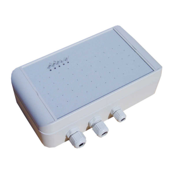
Summary of Contents for Feig Electronic OBID i-scan ID ISC.MR200-EP
- Page 1 MONTAGE ® OBID i-scan INSTALLATION ID ISC.MR200-EP ID ISC.MR200-W (deutsch / english) final public (B) 2008-03-12 M50808-4de-ID-B.doc...
- Page 2 ® OBID i-scan Montage / Installation ID ISC.MR200-W/EP deutsche Version ab Seite 3 english version from page 28 FEIG ELECTRONIC GmbH Seite 2 von 53 M50808-4de-ID-B.doc...
- Page 3 Hinweise jederzeit dankbar. Die in diesem Dokument gemachten Installationsempfehlungen gehen von günstigsten Rahmenbedingun- gen aus. FEIG ELECTRONIC GmbH übernimmt keine Gewähr für die einwandfreie Funktion in systemfrem- den Umgebungen. FEIG ELECTRONIC GmbH übernimmt keine Gewährleistung dafür, dass die in diesem Dokument enthal- tenden Informationen frei von fremden Schutzrechten sind.
-
Page 4: Table Of Contents
Gleichspannung am RF-Antennenanschluss X2............15 3.10 Eingänge ........................16 3.10.1 Optokoppler ......................16 3.11 Ausgänge ........................18 3.11.1 Optokoppler ......................18 3.11.2 Relais........................19 3.12 Schnittstellen .......................20 3.12.1 RS232-Schnittstelle ....................20 3.12.2 Ethernet Interface (ID ISC.MR200-EP)..............21 3.12.3 WLAN Interface (ID ISC.MR200-W) .................21 FEIG ELECTRONIC GmbH Seite 4 von 53 M50808-4de-ID-B.doc... - Page 5 ID ISC.MR200-W/EP Bedien- und Anzeigeelemente LED´s ..........................22 Inbetriebnahme Schnittstellenkonfiguration ..................23 5.1.1 Ethernet Interface(ID ISC.MR200-EP) ................23 5.1.2 WLAN Interface (ID ISC.MR200-W) ................24 Technische Daten Zulassung ........................27 6.1.1 Europa (CE) ........................27 6.1.2 USA (FCC) ........................27 FEIG ELECTRONIC GmbH Seite 5 von 53 M50808-4de-ID-B.doc...
-
Page 6: Sicherheits- Und Warnhinweise - Vor Inbetriebnahme Unbedingt Lesen
Obwohl dieses Gerät die zulässigen Grenzwerte für elektromagnetische Felder nicht über- schreitet, sollten Sie einen Mindestabstand von 25 cm zwischen dem Gerät und Ihrem Herz- schrittmacher einhalten und sich nicht für längere Zeit in unmittelbarer Nähe des Geräts bzw. der Antenne aufhalten. FEIG ELECTRONIC GmbH Seite 6 von 53 M50808-4de-ID-B.doc... -
Page 7: Leistungsmerkmale Der Readerfamilie Id Isc.mr200
ID ISC.MR200-E Asynchrone Schnittstelle RS232 und LAN Interface - Metallgehäuse ID ISC.MR200-EP Asynchrone Schnittstelle RS232 und LAN Interface - Kunststoffgehäuse ID ISC.MR200-W Asynchrone Schnittstelle RS232 und WLAN Interface - Kunststoffgehäuse Tabelle 2-1: Readertypen FEIG ELECTRONIC GmbH Seite 7 von 53 M50808-4de-ID-B.doc... -
Page 8: Lieferumfang
1 x Dichtverschluss - Reduzierstück ID ISC.MR200-W 1 x Reader ID ISC.MR200-W 1 x EMV-Ringkernferrit ∅ 28mm x 20 mm (Antennenzuleitung) 1 x Kurzschlussbrücke (Jumper) 1 x Dichtverschluss M16 Tabelle 2-2: Lieferumfang FEIG ELECTRONIC GmbH Seite 8 von 53 M50808-4de-ID-B.doc... -
Page 9: Montage Und Anschluss
Klemmbereich Beschreibung Verschraubung [mm] M 16 4,5 – 10 Anschlusskabel Antenne M 16 4,5 – 10 Eingänge / Ausgänge / Relais M 12 3,5 – 7 Spannungsversorgung Tabelle 3-1: Kabelverschraubungen ID ISC.MR200-W FEIG ELECTRONIC GmbH Seite 9 von 53 M50808-4de-ID-B.doc... -
Page 10: Montage Id Iscmr200-Ep
Relais / Ausgänge M 16 4,5 – 10 Eingänge M 12 3,5 – 7 Schnittstelle (seriell) M 12 3,5 – 7 Spannungsversorgung M 25 9 – 17 Ethernet Interface Tabelle 3-2: Kabelverschraubungen ID ISC.MR200-EP FEIG ELECTRONIC GmbH Seite 10 von 53 M50808-4de-ID-B.doc... -
Page 11: Dichtverschlüsse
Öffnungen eingesteckt. Bild 3-3: Deckelhalter 3.5 Designblenden Die Designblenden sind am Reader montiert. Die Vertiefung in der Mitte (Pfeil) dient zum verein- fachten Öffnen der Blende. Bild 3-4: Designblende FEIG ELECTRONIC GmbH Seite 11 von 53 M50808-4de-ID-B.doc... -
Page 12: Anschlussklemmen
® OBID i-scan Montage / Installation ID ISC.MR200-W/EP 3.6 Anschlussklemmen J3 J2 J1 V5 V4 V3 V2 V1 Bild 3-5: Anschlussklemmen Bild 3-6: Minimale Kabelkonfiguration ID ISC.MR200-W FEIG ELECTRONIC GmbH Seite 12 von 53 M50808-4de-ID-B.doc... -
Page 13: Antennenanschluss
Hierzu ist die Antennenzuleitung mindestens vier mal, eng anliegend durch den EMV-Ringkernferrit zu führen. Der Abstand zwischen Readeranschluss und Ring- kern sollte dabei maximal 20 cm betragen (siehe Bild 3-7). max. 20cm Bild 3-7: Antennenkabel mit EMV-Ringkernferrit FEIG ELECTRONIC GmbH Seite 13 von 53 M50808-4de-ID-B.doc... -
Page 14: Versorgungsspannung
Bei dem verwendeten Netzteil sollte es sich um eine SELV-Stromquelle begrenzter Leistung han- deln. Die Ausgangsleistung des Netzteils sollte min. 15 Watt betragen Ausgangsspannung 12 - 24 V ≥ 15 W Ausgangsleistung Tabelle 3-5: Elektrische Daten des externen Netzteils FEIG ELECTRONIC GmbH Seite 14 von 53 M50808-4de-ID-B.doc... -
Page 15: Gleichspannung Am Rf-Antennenanschluss X2
Beim Anschluss anderer Geräte (z.B. VSWR-Meter) ist darauf zu achten, dass diese auch für Gleichspannung geeignet sind. Bild 3-9: Position Jumper J10 Gleichspannung an Nein Antennenanschluss (Default) Tabelle 3-6: Konfiguration Jumper J10 FEIG ELECTRONIC GmbH Seite 15 von 53 M50808-4de-ID-B.doc... -
Page 16: Eingänge
Störungen zu Einbußen der Lesereichweite kommen kann. ID ISC.MR200 IN1+ ext. IN1- IN2+ ext. IN2- Bild 3-10: Interne und mögliche externe Beschaltung der Optokopplereingänge FEIG ELECTRONIC GmbH Seite 16 von 53 M50808-4de-ID-B.doc... - Page 17 5 V ... 10 V 270 Ω 11 V ... 15 V 560 Ω 16 V ... 20 V 820 Ω 21 V ... 24 V Tabelle 3-8: Benötigter externer Vorwiderstand R FEIG ELECTRONIC GmbH Seite 17 von 53 M50808-4de-ID-B.doc...
-
Page 18: Ausgänge
Verpolung oder Überlastung der Ausgänge führt zu deren Zerstörung. • Die Ausgänge sind nur zum Schalten ohmscher Lasten vorgesehen. ID ISC.MR200 O1-C O1-E ext. O2-C O2-E ext. Bild 3-11: Interne und mögliche externe Beschaltung der Optokopplerausgänge FEIG ELECTRONIC GmbH Seite 18 von 53 M50808-4de-ID-B.doc... -
Page 19: Relais
• Die Relaisausgänge sind nur zum Schalten ohmscher Lasten vorgesehen. Im Falle einer induktiven Last sind die Relaiskontakte durch eine externe Schutzbeschaltung zu schüt- zen. ID ISC.MR200 ext. Bild 3-12: Interne und mögliche externe Beschaltung des Relaisausgangs FEIG ELECTRONIC GmbH Seite 19 von 53 M50808-4de-ID-B.doc... -
Page 20: Schnittstellen
Bild 3-13: Verdrahtungsbeispiel für den Anschluss der RS232-Schnittstelle Hinweis: Wird auf dem PC/Notebook ein USB/RS232 Konverter benutzt, so sollte der COM-Port Pa- rameter „Char Timeout Multiplier“ von „1“ auf ca. „5“ erhöht werden. FEIG ELECTRONIC GmbH Seite 20 von 53 M50808-4de-ID-B.doc... -
Page 21: Ethernet Interface (Id Isc.mr200-Ep)
Receive Data - VETH- n.c. VETH- n.c. Tabelle 3-12: Pinbelegung Ethernet-Schnittstelle 3.12.3 WLAN Interface (ID ISC.MR200-W) Der Reader verfügt über eine integrierte drahtlose (802.11b) Ethernet Anbindung mit Datenraten bis zu 11 Mbit/s. FEIG ELECTRONIC GmbH Seite 21 von 53 M50808-4de-ID-B.doc... -
Page 22: Bedien- Und Anzeigeelemente
Reset. Leuchtet bei einer Warnung im RF-Teil des Readers. Der Fehlertyp kann per Software über den Befehl [0x6E] Rea- der Diagnostic gelesen werden. Tabelle 4-1: Konfiguration der LED FEIG ELECTRONIC GmbH Seite 22 von 53 M50808-4de-ID-B.doc... -
Page 23: Inbetriebnahme
IP-Adresse verfügt. Alle Reader verfügen über eine werksseitig voreingestellte IP- Adresse. Netzwerk Adresse IP-Adresse 192.168.10.10 Subnet-Mask 255.255.255.0 Port 10001 Tabelle 5-2: Standardkonfiguration des Ethernet Interfaces Hinweis: Die Reader müssen nacheinander ans Netzwerk angeschlossen und konfiguriert werden. FEIG ELECTRONIC GmbH Seite 23 von 53 M50808-4de-ID-B.doc... -
Page 24: Wlan Interface (Id Isc.mr200-W)
IP-Adresse verfügt. Alle Reader verfügen über eine werksseitig voreingestellte IP- Adresse. Alle Sicherheitsfunktionen sind werksseitig ausgeschaltet. Netzwerk Adresse IP-Adresse 172.168.10.10 Subnet-Mask 255.255.0.0 Port 10002 Tabelle 5-3: Standardkonfiguration des WLAN-Interfaces Hinweis: Die Reader müssen nacheinander ans Netzwerk angeschlossen und konfiguriert werden. FEIG ELECTRONIC GmbH Seite 24 von 53 M50808-4de-ID-B.doc... -
Page 25: Technische Daten
- 1 Relais ( 1 x Wechsler) • Eingänge – 2 Optokoppler max. 24 V DC/ 20 mA • Schnittstellen - ID ISC.MR200-EP RS232 und LAN (802.3) RS232 und WLAN (802.11b) - ID ISC.MR200-W FEIG ELECTRONIC GmbH Seite 25 von 53 M50808-4de-ID-B.doc... - Page 26 Angewendete Normen • Zulassung Funk - Europa EN 300 330 - USA FCC 47 CFR Part 15 • EN 301 489 • Sicherheit - Niederspannung EN 60950 - Human Exposure EN 50364 FEIG ELECTRONIC GmbH Seite 26 von 53 M50808-4de-ID-B.doc...
-
Page 27: Zulassung
Commission Rules permitting the operation of this device. Warning: Changes or modification made to this equipment not expressly approved by FEIG ELECTRONIC GmbH may void the FCC authorization to operate this equipment. Approval per FCC 47 CFR CH. I Part 15 applies to use with following antennas... -
Page 28: Feig Electronic Gmbh
ELECTRONIC GmbH does not give any guarantee promise for perfect function in cross environments. FEIG ELECTRONIC GmbH assumes no responsibility for the use of any information contained in this manual and makes no representation that they free of patent infringement. FEIG ELECTRONIC GmbH does not convey any license under its patent rights nor the rights of others. -
Page 29: Feig Electronic Gmbh
Inputs..........................41 3.10.1 Optocoupler ......................41 3.11 Outputs.........................43 3.11.1 Optocoupler ......................43 3.11.2 Relay.........................44 3.12 Interfaces ........................45 3.12.1 RS232 interface ......................45 3.12.2 Ethernet interface(ID ISC.MR200-EP) ..............46 3.12.3 WLAN-Interface (ID ISC.MR200-W) .................46 Operating and Display Elements FEIG ELECTRONIC GmbH Page 29 of 53 M50808-4de-ID-B.doc... -
Page 30: Feig Electronic Gmbh
Montage / Installation ID ISC.MR200-W/EP LED´s ..........................47 Startup Port configuration .......................48 5.1.1 Ethernet Interface(ID ISC.MR200-EP) ................48 5.1.2 WLAN Interface(ID ISC.MR200-W) ................49 Technical Specifications Approval ........................52 6.1.1 Europe (CE) ........................52 6.1.2 USA (FCC) ........................52 FEIG ELECTRONIC GmbH Page 30 of 53 M50808-4de-ID-B.doc... -
Page 31: Feig Electronic Gmbh
Although this device doesn't exceed the valid limits for electromagnetic fields you should keep a minimum distance of 25 cm between the device and your cardiac pacemaker and not stay in an immediate proximity of the device respective the antenna for some time. FEIG ELECTRONIC GmbH Page 31 of 53 M50808-4de-ID-B.doc... -
Page 32: Features Of The Reader Family Id Isc.mr200
Asynchronous interface RS232 and Ethernet Interface – metal housing ID ISC.MR200-EP Asynchronous interface RS232 and Ethernet Interface – plastic housing ID ISC.MR200-W Asynchrone Interface RS232 und WLAN Interface – plastic housing Table 2-1: Reader models FEIG ELECTRONIC GmbH Page 32 of 53 M50808-4de-ID-B.doc... -
Page 33: Scope Of Delivery
ID ISC.MR200-W 1 x Reader ID ISC.MR200-W 1 x EMC ring core ∅ 28mm x 20 mm (Antenna line) 1 x jumper 1 x seal cap M16 Table 2-2: Scope of delivery FEIG ELECTRONIC GmbH Page 33 of 53 M50808-4de-ID-B.doc... -
Page 34: Installation And Wiring
Description [mm] M 16 4.5 – 10 Antenna cable M 16 4.5 – 10 Inputs / Outputs / Relay M 12 3.5 – 7 Supply voltage Table 3-1: ID ISC.MR200-W cable glands FEIG ELECTRONIC GmbH Page 34 of 53 M50808-4de-ID-B.doc... -
Page 35: Installation Id Iscmr200-Ep
M 16 4,5 – 10 Inputs M 12 3,5 – 7 Interface (serial) M 12 3,5 – 7 Supply voltage M 25 9 – 17 Ethernet Interface Table 3-2: ID ISC.MR200-EP cable glands FEIG ELECTRONIC GmbH Page 35 of 53 M50808-4de-ID-B.doc... -
Page 36: Seal Caps
Fig. 3-3: Cover stay 3.5 Decorative covers The decorative covers are installed at the reader. The notch in the center (arrow) is used for opening the cover simplified. Fig. 3-4: Decorative cover FEIG ELECTRONIC GmbH Page 36 of 53 M50808-4de-ID-B.doc... -
Page 37: Wiring Terminals
® OBID i-scan Montage / Installation ID ISC.MR200-W/EP 3.6 Wiring terminals J3 J2 J1 V5 V4 V3 V2 V1 Fig. 3-5: Wiring terminals Fig. 3-6: Minimum cable configuration (shown: ID ISC.MR200-W) FEIG ELECTRONIC GmbH Page 37 of 53 M50808-4de-ID-B.doc... -
Page 38: Antenna Connection
EMC ferrite ring core at least 4 times. The distance between the Reader connection and the ring core should be no greater than 20 cm (see Fig. 3-7). max. 20cm Fig. 3-7: Antenna cable with EMC ferrite ring core FEIG ELECTRONIC GmbH Page 38 of 53 M50808-4de-ID-B.doc... -
Page 39: Supply Voltage
The power supply should be a Safety Extra-Low Voltage (SELV) type with limited power. The output power of the power supply should be at least 15 watts. Output voltage 12 - 24 V ≥ 15 W Output power Table 3-5: Electrical specifications for external power supply FEIG ELECTRONIC GmbH Page 39 of 53 M50808-4de-ID-B.doc... -
Page 40: Dc Voltage On The Rf Antenna Terminal X2
By connecting other devices (e.g. VSWR-Meter) it must be checked if these devices are suitable for DC voltage. Fig. 3-9: Position Jumper J10 DC voltage on antenna terminal (Default) Table 3-6: Jumper J10 configuration FEIG ELECTRONIC GmbH Page 40 of 53 M50808-4de-ID-B.doc... -
Page 41: Inputs
The Reader supply voltage must not be used to drive the inputs, since otherwise additionally induced noise may reduce the effective reading range. ID ISC.MR200 IN1+ ext. IN1- IN2+ ext. IN2- Fig. 3-10: Internal and possible external wiring of the optocoupler inputs FEIG ELECTRONIC GmbH Page 41 of 53 M50808-4de-ID-B.doc... -
Page 42: Feig Electronic Gmbh
5 V ... 10 V 270 Ω 11 V ... 15 V 560 Ω 16 V ... 20 V 820 Ω 21 V ... 24 V Table 3-8: Required external series resistance R FEIG ELECTRONIC GmbH Page 42 of 53 M50808-4de-ID-B.doc... -
Page 43: Outputs
Reversing the polarity or overloading the outputs will destroy them. • The outputs are intended for switching resistive loads only. ID ISC.MR200 O1-C O1-E ext. O2-C O2-E ext. Fig. 3-11: Internal and possible external wiring of the optocoupler outputs FEIG ELECTRONIC GmbH Page 43 of 53 M50808-4de-ID-B.doc... -
Page 44: Relay
• The relay outputs are intended for switching resistive loads only. If an inductive load is used, the relay contacts must be protected by means of an external protection circuit. ID ISC.MR200 ext. Fig. 3-12: Internal and possible external wiring of the relay output FEIG ELECTRONIC GmbH Page 44 of 53 M50808-4de-ID-B.doc... -
Page 45: Interfaces
Fig. 3-13: Wiring example for connecting the RS232 interface Note: If there is an USB/RS232 converter used on the PC/Notebook side, we recommend to in- crease the „Char Timeout Multiplier“ parameter in the COM-Port settings from „1“ to about „5“. FEIG ELECTRONIC GmbH Page 45 of 53 M50808-4de-ID-B.doc... -
Page 46: Ethernet Interface(Id Isc.mr200-Ep)
Table 3-12: Ethernet interface pin assignments 3.12.3 WLAN-Interface (ID ISC.MR200-W) The Reader has an integrated wireless (802.11b) Ethernet interface with data-rates up to 11 Mbit/s. Terminal X8 serves as the Ethernet port. FEIG ELECTRONIC GmbH Page 46 of 53 M50808-4de-ID-B.doc... -
Page 47: Operating And Display Elements
Comes on when there is a warning in the RF section of the Reader. The error type can be read via software using the Reader Diagnostic command [0x6E]. Table 4-1: LED configuration FEIG ELECTRONIC GmbH Page 47 of 53 M50808-4de-ID-B.doc... -
Page 48: Startup
All Readers have been assigned a factory default IP address. Network Address IP address 192.168.10.10 Subnet mask 255.255.255.0 Port 10001 Table 5-2: Standard configuration of the Ethernet interface Note: The Readers must be connected to the network and configured in succession. FEIG ELECTRONIC GmbH Page 48 of 53 M50808-4de-ID-B.doc... -
Page 49: Wlan Interface(Id Isc.mr200-W)
All Readers have been assigned a factory default IP address. Network Address IP address 172.168.10.10 Subnet mask 255.255.0.0 Port 10002 Table 5-3: Standard configuration of the WLAN interface Note: The Readers must be connected to the network and configured in succession. FEIG ELECTRONIC GmbH Page 49 of 53 M50808-4de-ID-B.doc... -
Page 50: Technical Specifications
- 1 relay ( 1 x changeover) • Inputs – 2 optocoupler max. 24 V DC/ 20 mA • Interfaces – ID ISC.MR200-EP RS232 and LAN (802.3) – ID ISC.MR200-W RS232 and WLAN (802.11b) FEIG ELECTRONIC GmbH Page 50 of 53 M50808-4de-ID-B.doc... -
Page 51: Feig Electronic Gmbh
Applicable Standards • RF approval - Europe EN 300 330 - USA FCC 47 CFR Part 15 • EN 301 489 • Safety - Low Voltage EN 60950 - Human Exposure EN 50364 FEIG ELECTRONIC GmbH Page 51 of 53 M50808-4de-ID-B.doc... -
Page 52: Approval
Commission Rules permitting the operation of this device. Warning: Changes or modification made to this equipment not expressly approved by FEIG ELECTRONIC GmbH may void the FCC authorization to operate this equipment. Approval per FCC 47 CFR CH. I Part 15 applies to use with following antennas... - Page 53 ® OBID i-scan Montage / Installation ID ISC.MR200-W/EP FEIG ELECTRONIC GmbH Page 53 of 53 M50808-4de-ID-B.doc...
Need help?
Do you have a question about the OBID i-scan ID ISC.MR200-EP and is the answer not in the manual?
Questions and answers