
Related Manuals for Feig Electronic OBID i-scan UHF


Summary of Contents for Feig Electronic OBID i-scan UHF
- Page 1 INSTALLATION ID ISC.MRU102-PoE / ID ISC.MRU102-USB Housed Version final – public (B 2012-08-09 – M20711-0e-ID-B.docx...
- Page 2 FEIG ELECTRONIC call explicit attention that devices which are subject of this document are not designed with components and testing methods for a level of reliability suitable for use in or in connection with surgical implants or as critical components in any life support systems whose failure to perform can reasonably be expected to cause significant injury to a human.
- Page 3 • The following figure formats are used: 0...9: for decimal figures 0x00...0xFF: for hexadecimal figures, b0...1 for binary figures. • The hexadecimal value in brackets "[ ]" marks a control byte (command). FEIG ELECTRONIC GmbH Page 3 of 21 M20711-0e-ID-B.docx...
-
Page 4: Table Of Contents
4.5. USB-Interface on X3 (Host Communication) ..............14 5. Control and Display Elements 5.1. LED ........................... 15 6. Technical Data 7. Radio Approvals 7.1. Europe (CE) ........................18 7.2. Declaration of Conformity ....................19 ANNEX FEIG ELECTRONIC GmbH Page 4 of 21 M20711-0e-ID-B.docx... - Page 5 ® OBID i-scan Installation ID ISC.MRU102-PoE/-USB ANNEX A - Accessories ......................20 ANNEX B – Wall Mounting Kit ID ISC.MS.MR/PR-A .............. 21 FEIG ELECTRONIC GmbH Page 5 of 21 M20711-0e-ID-B.docx...
- Page 6 Although this device doesn't exceed the valid limits for electromagnetic fields you should keep a minimum distance of 25 cm between the device and your cardiac pacemaker and not stay in an immediate proximity of the device respective the antenna for some time. FEIG ELECTRONIC GmbH Page 6 of 21 M20711-0e-ID-B.docx...
-
Page 7: Performance Features Of The Reader
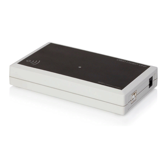
ID ISC.MRU102-PoE Housed version with LAN Interface and Power over Ethernet (PoE) ID ISC.MRU102-USB Housed version with USB Interface Table 1: Reader types 2.2. Optional Accessories Optional Accessories are listed in the appendix. FEIG ELECTRONIC GmbH Page 7 of 21 M20711-0e-ID-B.docx... -
Page 8: Assembly And Wiring
(see Appendix:ANNEX A1 – Wall Mounting Kit ID ISC.MS.MR/PR-A) NOTE: Before any installation the intended position of the reader should be tested for its suitabili- 3.1.1. Dimensions Figure 1: Dimensions of the housing version (all dimensions are in mm) FEIG ELECTRONIC GmbH Page 8 of 21 M20711-0e-ID-B.docx... -
Page 9: Connections
Figure 2: Connection overview Connector Description ANT 1 Antenna Terminal ANT1 (Impedance 50Ohm) Power supply 12 - 24VDC USB Interface 10/100Tbase Ethernet interface with RJ-45 (PoE) Table 2: Connectors FEIG ELECTRONIC GmbH Page 9 of 21 M20711-0e-ID-B.docx... -
Page 10: Antenna Terminal Ant1
40 cm. In combination with a near field transponder the maximum read range is approx. 5 cm. Figure 3: Position of the internal antenna FEIG ELECTRONIC GmbH Page 10 of 21 M20711-0e-ID-B.docx... -
Page 11: Power Supply
Ambient Operating Temperature: 0°C to +40°C 3887.000.00 ID NET.12V-B-US Table 5: Recommended power supply NOTE: The power supply is supplied with a DC/ plug 2.5mm x 5.5mm. This is compatible with the readers socket X1. FEIG ELECTRONIC GmbH Page 11 of 21 M20711-0e-ID-B.docx... -
Page 12: Power Supply Via Power Over Ethernet (Poe)
PoE - power supply recommendations: Article No. Name Description Power over Ethernet Supply 100-240V AC 3842.000.00 ID NET.PoEI13W-A (Continental European Plug), Output: 48V DC/ ; 0,5A Table 6: Recommended PoE Power Supply FEIG ELECTRONIC GmbH Page 12 of 21 M20711-0e-ID-B.docx... -
Page 13: Ethernet-Interface On X4 (10/100Tbase)
10001 DHCP Table 7: Standard factory configuration of the Ethernet connection NOTE: The reader provides a DHCP able TCP/IP interface. It is recommended to use a shielded twisted pair STP CAT5 cable. FEIG ELECTRONIC GmbH Page 13 of 21 M20711-0e-ID-B.docx... -
Page 14: Usb-Interface On X3 (Host Communication)
The length of the USB-cable can be a max. of 5 meter. It isn’t allowed to use longer cables! The reader must be powered with a external power supply even if it is connected to a “high powered port”. FEIG ELECTRONIC GmbH Page 14 of 21 M20711-0e-ID-B.docx... -
Page 15: Control And Display Elements
Flashes if RF-Warning (red – green alternating with 8Hz) (Temperature alarm, short circuit on antenna output) „INITIALIZING“ LED orange Flashes during Reader initialization after power-up. Table 8: Default configuration of the LEDs FEIG ELECTRONIC GmbH Page 15 of 21 M20711-0e-ID-B.docx... -
Page 16: Technical Data
860 MHz – 960 MHz Max. 500 mW ± 1,5 dB RF-Power 1 x SMA female(50 Ω) Antenna Connector 1 x integrated Antenna (ANT4) Interfaces • ID ISC.MRU102-USB USB (Full Speed) • ID ISC.MRU102-PoE Ethernet (TCP/IP) FEIG ELECTRONIC GmbH Page 16 of 21 M20711-0e-ID-B.docx... - Page 17 * Caution: Overheating of the device may result in performance losses. It is recommended to activate the RF of the reader only if there is a transponder in the detection range of an antenna. FEIG ELECTRONIC GmbH Page 17 of 21...
-
Page 18: Radio Approvals
When used according to regulation, this radio equipment conforms with the basic requirements of Article 3 and the other relevant provisions of the R&TTE Guideline 1999/E6 dated March 99. Equipment Classification according to ETSI EN 301 489: Class 2 FEIG ELECTRONIC GmbH Page 18 of 21 M20711-0e-ID-B.docx... -
Page 19: Declaration Of Conformity
® OBID i-scan Installation ID ISC.MRU102-PoE/-USB 7.2. Declaration of Conformity FEIG ELECTRONIC GmbH Page 19 of 21 M20711-0e-ID-B.docx... -
Page 20: Annex
Power over Ethernet Supply 100-240V AC 3842.000.00 ID NET.PoEI13W-A (Continental European Plug), Output: 48V DC/ ; 0,5A 1686.000.00 ID CAB.USB-A USB-cable 2,5m Wall mounting kit for 1691.000.01 ID ISC.MS.MR/PR-A ID ISC.MR102 Table 9: Accessories FEIG ELECTRONIC GmbH Page 20 of 21 M20711-0e-ID-B.docx... - Page 21 Remove the screws from the back side of the Reader. • Attach the individual wall hangers using the screws supplied with the mounting kit. Figure 6: Mounting wall hangers Figure 7: Mounting drill dimensioning (all dimensions in mm) FEIG ELECTRONIC GmbH Page 21 of 21 M20711-0e-ID-B.docx...
Need help?
Do you have a question about the OBID i-scan UHF and is the answer not in the manual?
Questions and answers