Belmont CREDIA G1 Installation Instructions Manual
Dental unit
Hide thumbs
Also See for CREDIA G1:
- Operating instructions manual (49 pages) ,
- Instructions for use manual (20 pages)
Table of Contents
Advertisement
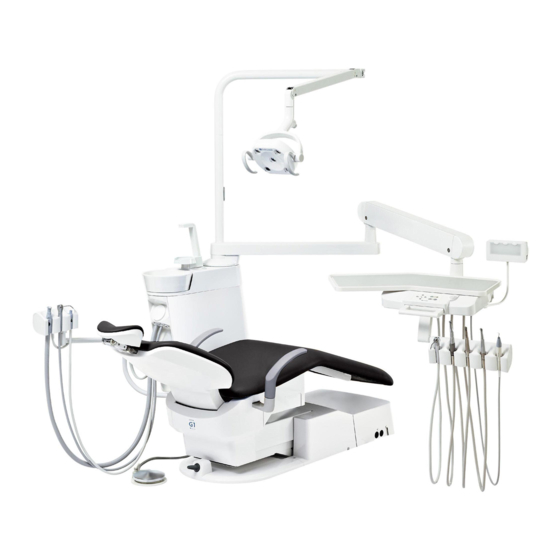
DENTAL UNIT
INSTALLATION INSTRUCTIONS
This manual provides installation instructions for the CREDIA G1.
The instructions contained in this booklet should be thoroughly read and
understood before installing the chair and unit.
After the installation has been completed, keep this manual in a safe place and
refer to it for future maintenance.
IMPORTANT
BOOK NO. 1E03V5C0 (3E)
Printed in Vietnam 2013-12
Advertisement
Table of Contents

Related Manuals for Belmont CREDIA G1


Summary of Contents for Belmont CREDIA G1
- Page 1 DENTAL UNIT INSTALLATION INSTRUCTIONS IMPORTANT This manual provides installation instructions for the CREDIA G1. The instructions contained in this booklet should be thoroughly read and understood before installing the chair and unit. After the installation has been completed, keep this manual in a safe place and...
-
Page 3: Table Of Contents
TABLE OF CONTENTS Page 1. Overview and Major Components ---------------------------------------------------1 2. Specifications and Dimensions 2-1. Unit Section Specifications ---------------------------------------------------------------1 2-2. Unit Section Dimensions ------------------------------------------------------------------2 3. Installation Requirements ------------------------------------------------------------ 3 ~ 5 4. Installation Instructions 4-1. Unit Section Unpacking -------------------------------------------------------------------6 4-2. Chair Section Preparation ---------------------------------------------------------------6 4-3. -
Page 4: Overview And Major Components
Weight : 70kg (Without dental light) Dental Light : 300LED Dental light (Type 320M) Chair : CREDIA G1 Chair Usage environment : Temperature +10ºC ~ +40ºC Humidity 30% ~ 75% Air pressure 700 hPa ~ 1060 hPa Transportation / Storage environment : Temperature -20ºC ~ +70ºC... -
Page 5: Unit Section Dimensions
2-2. DIMENSIONS Over the Patient, Holder Type Unit : mm Dimensional tolerance: ±10% 1024 1215 Over the Patient, Rod Type (Continental Type) 1100 1215 - 2 -... -
Page 6: Installation Requirements
(2) The CREDIA G1 should be mounted taking the opening end of drain pipe into due consideration. (3) The area on which the CREDIA G1 is to be installed must have endurance force of 490kg/m (4) The installation position of the CREDIA G1 is shown in Fig-3 as a recommended example. - Page 7 Electric Supply Requirements (1) The connection of the power supply cable is to be carried out in accordance with the local electrical regulation. (2) Capacity of the power supply (Include the CREDIA G1 Chair) 110V Type Single Phase 60 Hz...
- Page 8 Unit : mm Dimensional tolerance: ±10% Chair Base Installation reference point (Drain) min.1000 min.800 Air Supply Installation reference point (Drain) Power Vacuum Operating Wire Source Water Supply Vacuum Pipe PT1/2 Floor Line Air Supply Water Installation reference point (Drain) Vacuum Pipe Supply Vacuum Operating Wire Power Source...
-
Page 9: Installation Instructions
4. Installation Instructions 4-1. Unit Section Unpacking 1. Remove all staples fixing the carton to the pallet and lift up to remove the carton. 2. Installation parts and accessory parts are packing in the small carton boxes. Open the parts boxes and check the contents of each packing with the accessory parts list attached in the parts box. -
Page 10: Unit Section Preparation
4-3. Unit Section Preparation 1. Loosen the side cover fixing screw by flat head screwdriver on the rear side of the cuspidor unit. Open the side cover to outside as shown on the below figure. 2. Remove four cuspidor fixing bolts (M10 x 60) and hold the cuspidor unit. Four cap bolts are used when fix the cuspidor to the chair. -
Page 11: Fixing The Unit Hose To The Chair
4-5. Fixing the Unit Hose to the Chair Pass the vacuum hose, drain hose, tubings and wires from cuspidor to the junction box through to inside of the chair. Junction Box Cuspidor Unit Chair 1. Remove the front flange cover from the chair. Front Flange Cover 2. -
Page 12: Installation Of Junction Box (Plumbing)
3. Pass through the hoses into the bracket and right side of the lower flange. Run the hoses to hole in the junction box. Hole in a junction box Bracket 4. Fix the junction box to the floor with two M3.5 x 20 wood screws. M3.5 x 20 Wood Screws 4-6. -
Page 13: Tubing Connections In The Junction Box
3. Connect Water Shut Off Valve and Water Filter with Stainless Flexible Pipe and Packing. Connect Air Shut Off Valve and Air Filter in the same way. Connect with plastic glue Drain Hose Vacuum Hose Air Vacuum Connection Vacuum Elbow Drain Elbow Drain Joint (Optional) -
Page 14: Electrical Connections In The Junction Box
4-8. Electrical Connections in The Junction Box * Turn off the main switch before connect the wirings. 1. Connect the central vacuum operating wires from floor, water heater wires (Blue, Brown) from cuspidor and 24V from doctor table (Red, Black) to the terminal block. Be sure to connect the earth wires from doctor table and cuspidor into the junction box. -
Page 15: Installation Of The Dental Light
4-9. Installation of the Dental Light * Refer to the dental light installation manual for installing the dental light. 1. Pass the light cable through the L-type light pole and insert the balance arm joint into the light pole, fix it with two M6 button screws supplied with dental light. - Page 16 3. Pass the light cable through the main post and hole of the mounting bracket. Connect the 2P, 3P and 4P connectors from the dental light to the connectors from the junction box in the cuspidor unit. Main post Mounting bracket Connector 4.
-
Page 17: Installation Of Accessories
5. Installation of Accessories 5-1. Cuspidor Bowl, Drain Cap and Basket Strainer Insert the cuspidor bowl to the cuspidor unit. Fit the drain cap and the basket strainer in the cuspidor bowl. * To easily attach the cuspidor bowl, moist the insertion part, rotate and push down the cuspidor bowl. Drain Cap Basket Strainer Cuspidor Bowl... -
Page 18: Dental Viewer
5-4. Dental Viewer 1. Pass the viewer cable through to the table chassis and connect to the terminal block. 2. Fix the dental viewer bracket to the table chassis with two M4 x 15 3A sems screws. M4 x 15 (2 pcs.) 3A Sems Screw Table chassis Terminal block... -
Page 19: Monitor Bracket
5-7. Table Tray and Table Tray Mat (Holder Type) Fix the table tray to the table chassis with five M5 x 40 pan head screws. Place the table tray mat on the table tray. Table Tray Mat Table Tray Table Chassis Pan Head Screw M5 x 40 (5 pcs.) 5-8. -
Page 20: Rod, Fix The Hose To The Rod (Rod Type/Continental Type)
5-9. Rod, Fix the hose to the rod (Rod Type/Continental Type) Lift up the rod holder and insert the rod part into the rod holder. Rod Holder Attach the O-ring to prevent the handpiece hose slipping off from the rod. In case of the scaler hose, pass the silicone tube and heat shrink rubber tube through to the scaler hose to hold it into the rod. -
Page 21: Attach The Cover
6. Attach the Cover After the wirings, tubings and installation of the accessory parts has been completed, attach the covers to the unit. Refer to the chair installation manual for attach the covers to the chair. 6-1. Attach the Cuspidor Cover Attach the side covers to the cuspidor. -
Page 22: Adjustment
7. Adjustment 7-1. Water and Air Stop Valves Open the water stop valve and the air stop valve in the junction box section. Turn on the main switch and check that water and air are not leaking. 7-2. Main Air Pressure The main air pressure has been adjusted in the factory. -
Page 23: Handpiece Adjustment (Drive Air)
7-5. Handpiece Adjustment (Drive Air) Each handpiece drive air can be adjusted by turning the drive air adjustment screw during the operation. Drive air pressure is decrease by turning the adjustment screw clockwise and increase by turning the adjustment screw counterclockwise use a flat head screwdriver. Drive air pressure is indicated on the handpiece pressure gauge located on the rear side of table and set the drive air pressure according to the instruction manual attached to individual handpiece. -
Page 24: Unit Flow Diagram
8. Unit Flow Diagram 8-1. Doctor Table Section - 21 -... -
Page 25: Cuspidor & Junction Box Section (Central Vacuum, Central Saliva Ejector, Clean Water System Specifications)
8-2. Cuspidor & Junction Box Section (Central Vacuum, Central Saliva Ejector, Clean Water System Specifications) - 22 -... -
Page 26: Cuspidor & Junction Box Section (Air Vacuum, Air Saliva Ejector Specifications)
8-3. Cuspidor & Junction Box Section (Air Vacuum, Air Saliva Ejector Specifications) - 23 -... -
Page 27: Unit Electrical Diagram
9. Unit Electrical Diagram Chair Dr.Table Section XM9P XM9P Plug Chair Operating Wire (Unit Side) Brown 1:Brown Orange 2:Red To chair pcb. Yellow 3:Orange CN4-1 Black Green Membrane Switch Wire 4:Yellow (Switch input) Blue 5:Green LED Drive Board Violet 6:Blue Grey 7:Violet Black... - Page 28 NOTE BELMONT MANUFACTURING CO., LTD. (Manufacturer) Long Duc Industrial Park, Long Thanh District, Dong Nai Province, Viet Nam TEL : +84-613-201-100 / FAX : +84-613-201-096 TAKARA BELMONT CORPORATION 2-1-1, Higashishinsaibashi,Chuo-ku,Osaka, 542-0083,Japan TEL : +81-6-6213-5945 / FAX : +81-6-6212-3680 www.takara-net.com...
Need help?
Do you have a question about the CREDIA G1 and is the answer not in the manual?
Questions and answers