Table of Contents
Advertisement
Quick Links
Advertisement
Table of Contents

Related Manuals for Supermicro GS7


Summary of Contents for Supermicro GS7
- Page 1 GS7 Chassis USER’S MANUAL Revision 1.0...
- Page 2 State of California, USA. The State of California, County of Santa Clara shall be the exclusive venue for the resolution of any such disputes. Supermicro's total liability for all claims will not exceed the price paid for the hardware product.
- Page 3 About this Manual This manual is written for professional system integrators and PC technicians. It provides information for the installation and use of the GS7 chassis. Installation and maintenance should be performed by experienced technicians only. This document lists compatible parts available when this document was published. Refer to...
-
Page 4: Table Of Contents
Supermicro GS7 Chassis Series User's Manual Contents Contacting Supermicro ......................6 Chapter 1 Introduction 1-1 Overview ..........................7 Key Features ........................7 1-2 Components .........................8 Drives ..........................8 Fans and Cooling ........................8 Motherboard ........................8 Expansion Slots ........................8 External I/O Connections ....................8 Control Panel ........................8 1.3 Chassis Features .........................9... - Page 5 Preface 2-6 Fans and Cooling .......................23 Air Flow ..........................23 Dust Filters ........................23 Liquid Cooling ........................27 2-7 Installing Expansion Cards ....................28 2-8 Installing GPUs ........................29 2-9 Power Supply ........................31 Appendix A Standardized Warning Statements for AC Systems...
-
Page 6: Contacting Supermicro
Supermicro GS7 Chassis Series User's Manual Contacting Supermicro Headquarters Address: Super Micro Computer, Inc. 980 Rock Ave. San Jose, CA 95131 U.S.A. Tel: +1 (408) 503-8000 Fax: +1 (408) 503-8008 Email: marketing@supermicro.com (General Information) support@supermicro.com (Technical Support) Website: www.supermicro.com Europe Address: Super Micro Computer B.V. -
Page 7: Chapter 1 Introduction
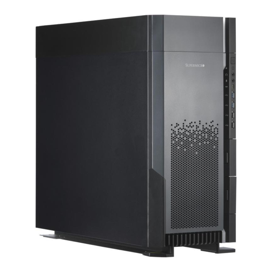
Chapter 1: Introduction Chapter 1 Introduction 1-1 Overview Supermicro's GS7 gaming chassis (GS7) offers extreme storage and cooling opportunities in a sleek, attractive form. It can house motherboards up to an EATX form factor to support outstanding gaming-level high performance. Key Features •... -
Page 8: Components
Supermicro GS7 Chassis User's Manual 1-2 Components The primary components are described below. Drives The standard configuration includes two 5.25" drive bays, two front access 2.5" drive trays, and a removable internal drive cage with four 3.5" tool-less drive trays. -
Page 9: Chassis Features
Chapter 1: Introduction 1.3 Chassis Features Control Panel Power and LED buttons are located on the control panel on the front of the chassis along with several USB ports. An LED bar runs along the front of the chassis. Power Button LED Button Type C USB 2.0... -
Page 10: Chassis Front
Supermicro GS7 Chassis User's Manual Chassis Front The illustration below shows the features included on the front of the chassis. Figure 1-2. Front View Chassis Front Features Item Features Description Control Panel See previous page for details. Drive Bay Latch Latch to open 2.5"... -
Page 11: Chassis Rear
Chapter 1: Introduction Chassis Rear The illustration below shows the features included on the rear of the chassis. Figure 1-3. Rear View Chassis Rear Features Item Features Description Cover Cover for access to top filter for optional liquid cooling installation Rear 12-cm fan Rear I/O ports. -
Page 12: Where To Get Replacement Components
(http://www.supermicro.com/ support/rma/). Whenever possible, repack the chassis in the original Supermicro carton, using the original packaging material. If these are no longer available, be sure to pack the chassis securely, using packaging material to surround the chassis so that it does not shift within the carton and become damaged during shipping. -
Page 13: Chapter 2 Chassis Setup And Maintenance
Chapter 2: Server Installation Chapter 2 Chassis Setup and Maintenance 2-1 Overview This chapter covers the steps required to install components and perform maintenance on the chassis. Most tasks can be accomplished without tools. Review the warnings and precautions listed in the manual before setting up or servicing this chassis, including those in the system safety appendix. -
Page 14: Removing Power From The System
Supermicro GS7 Chassis User's Manual 2-2 Removing Power from the System Before performing most setup or maintenance tasks, use the following procedure to ensure that power has been removed from the system. 1. Use the operating system to power down the system, following the on-screen prompts. -
Page 15: Removing The Chassis Covers
Chapter 2: Server Installation 2-3 Removing the Chassis Covers Caution: Except for short periods of time, do not operate the system without the cover in place. The chassis cover must be in place to allow proper airflow and prevent overheating. Left Side and Right Side Covers Removing the Left Side Chassis Cover Begin by powering down the system. -
Page 16: Installing The Motherboard
Supermicro GS7 Chassis User's Manual 2-4 Installing the Motherboard I/O Shield This shield encloses the I/O ports at the rear of the chassis. Install it before installing the motherboard. The motherboard package should include a compatible shield. Installing the I/O Shield 1. - Page 17 Chapter 2: Server Installation Figure 2-3. Installing the Motherboard...
-
Page 18: Front Bezel
Supermicro GS7 Chassis User's Manual Removing the Right Side Chassis Cover Begin by powering down the system. 1. Remove the two thumb screws at the rear of the chassis. 2. Slide the cover back to remove it from the chassis. -
Page 19: Installing Storage Drives
Chapter 2: Server Installation 2-5 Installing Storage Drives Drive Cage The removable drive cage is accessed by removing the left chassis cover. These drives are not hot-swap, power must be removed from the system before removing or installing drives. The cage can house up to four drives of either 3.5" or 2.5" (2.5" drives require an optional bracket: MCP-220-73102-0N). -
Page 20: Top Front Peripheral Drive Bays
Supermicro GS7 Chassis User's Manual Top Front Peripheral Drive Bays Two 5.25" peripheral tool-less drive bays are located at the top front of the chassis. These drives are not hot-swap, power must be removed from the system before removing or installing drives. -
Page 21: Front Side Drive Bays
Chapter 2: Server Installation Front Side Drive Bays Two 2.5" drive bays are included along the front right side of the chassis. These drives are not hot-swap, power must be removed from the system before removing or installing drives. Installing/Removing the Front Side Drive Bays Begin by powering down the system. -
Page 22: Installing And Removing Drives From Trays
Supermicro GS7 Chassis User's Manual Installing and Removing Drives from Trays The drives must be inserted into tool-less drive trays before being installed in the system. Installing a Drive into a Drive Tray 1. Pull out the two securing tabs on the tray as illustrated below. -
Page 23: Fans And Cooling
Chapter 2: Server Installation 2-6 Fans and Cooling The chassis includes two front intake fans and one rear exhaust fan. The top of the chassis can accommodate up to three optional 12-cm fans or an optional liquid cooling unit. Air Flow Make sure cables do not obstruct the cooling airflow. - Page 24 Supermicro GS7 Chassis User's Manual 5. Lift the top panel up and out of the chassis. 6. Remove the screws that secure the filter to the top panel and remove the filter. (The filter is washable and should be cleaned as needed.) 7.
- Page 25 Chapter 2: Server Installation Replacing Front Fans 1. Open the front bezel to access the front fan area. 2. Disconnect the fan wiring. 3. If existing fans are mounted with rubber pins, pull the fans toward you. If the fans are mounted by screws, unscrew the fans.
- Page 26 Supermicro GS7 Chassis User's Manual Replacing the Rear Fan 1. Open the left side cover for access to the rear fan. 2. Remove the screws at the top back of the chassis that secure the fan to the chassis. 3. Pull the fan out through the open space inside the chassis.
-
Page 27: Liquid Cooling
Chapter 2: Server Installation Liquid Cooling The GS7 may be outfitted with a liquid cooling system that installs in the top panel. Installing a Liquid Cooling Unit 1. Begin by removing the screw from the top chassis cover. 2. Once the screw has been removed, slide the cover toward the back of the chassis. -
Page 28: Installing Expansion Cards
Supermicro GS7 Chassis User's Manual 2-7 Installing Expansion Cards Installing an Expansion Card 1. Power down the system as described in section 2-2 and open the left side chassis cover. 2. Remove the left chassis cover. 3. Push in the long release tab on the right side and the small one on the left side of the cover to detach and remove the cover completely. -
Page 29: Installing Gpus
Chapter 2: Server Installation 2-8 Installing GPUs Installing a GPU with Bracket and Holder 1. Align the screw holes of the GPU with the bracket by standing the gold finger on the surface. 2. Tighten two screws to secure the GPU to the bracket. Figure 2-16. - Page 30 Supermicro GS7 Chassis User's Manual Figure 2-18. Installing the GPU to the Motherboard...
-
Page 31: Power Supply
Chapter 2: Server Installation 2-9 Power Supply The GS7 chassis can accommodate any standard PS2 size power supply. Mount the power supply on the rear floor of the chassis with the power supply fan facing down. It is recommended that the power requirements of installed components in the system total no more than 80% of the power supply rating. - Page 32 9. The 2000W power supply that comes standard with the GS7 is a modular type power supply that allows you to connect only the wiring you need for your system's configuration.
-
Page 33: Appendix A Standardized Warning Statements For Ac Systems
Supermicro's Technical Support department for assistance. Only certified technicians should attempt to install or configure components. Read this appendix in its entirety before installing or configuring components in the Supermicro chassis. These warnings may also be found on our website at http://www.supermicro.com/about/... - Page 34 Appendix A: Standardized Warning Statements Warnung WICHTIGE SICHERHEITSHINWEISE Dieses Warnsymbol bedeutet Gefahr. Sie befinden sich in einer Situation, die zu Verletzungen führen kann. Machen Sie sich vor der Arbeit mit Geräten mit den Gefahren elektrischer Schaltungen und den üblichen Verfahren zur Vorbeugung vor Unfällen vertraut. Suchen Sie mit der am Ende jeder Warnung angegebenen Anweisungsnummer nach der jeweiligen Übersetzung in den übersetzten Sicherheitshinweisen, die zusammen mit diesem Gerät ausgeliefert wurden.
- Page 35 Supermicro GS7 Chassis User's Manual . ٌ ا ك ً ف حالة و ٌ يك أى تتسبب ف اصابة جسذ ة ٌ هذا الزهز ع ٌ خطز !تحذ ز قبل أى تعول عىل أي هعذات،يك عىل علن بالوخاطز ال ا ٌجوة عي الذوائز...
- Page 36 Appendix A: Standardized Warning Statements Warnung Vor dem Anschließen des Systems an die Stromquelle die Installationsanweisungen lesen. ¡Advertencia! Lea las instrucciones de instalación antes de conectar el sistema a la red de alimentación. Attention Avant de brancher le système sur la source d'alimentation, consulter les directives d'installation. .יש...
- Page 37 Supermicro GS7 Chassis User's Manual Warnung Dieses Produkt ist darauf angewiesen, dass im Gebäude ein Kurzschluss- bzw. Überstromschutz installiert ist. Stellen Sie sicher, dass der Nennwert der Schutzvorrichtung nicht mehr als: 250 V, 20 A beträgt. ¡Advertencia! Este equipo utiliza el sistema de protección contra cortocircuitos (o sobrecorrientes) del edificio.
- Page 38 Appendix A: Standardized Warning Statements Power Disconnection Warning Warning! The system must be disconnected from all sources of power and the power cord removed from the power supply module(s) before accessing the chassis interior to install or remove system components. 電源切断の警告...
- Page 39 Supermicro GS7 Chassis User's Manual אזהרה מפני ניתוק חשמלי !אזהרה יש לנתק את המערכת מכל מקורות החשמל ויש להסיר את כבל החשמלי מהספק .לפני גישה לחלק הפנימי של המארז לצורך התקנת או הסרת רכיבים يجب فصم اننظاو من جميع مصادر انطاقت وإ ز انت سهك انكهرباء من وحدة امداد...
- Page 40 Appendix A: Standardized Warning Statements Attention Il est vivement recommandé de confier l'installation, le remplacement et la maintenance de ces équipements à des personnels qualifiés et expérimentés. !אזהרה .צוות מוסמך בלבד רשאי להתקין, להחליף את הציוד או לתת שירות עבור הציוד واملدربيه...
- Page 41 Supermicro GS7 Chassis User's Manual Warnung Diese Einheit ist zur Installation in Bereichen mit beschränktem Zutritt vorgesehen. Der Zutritt zu derartigen Bereichen ist nur mit einem Spezialwerkzeug, Schloss und Schlüssel oder einer sonstigen Sicherheitsvorkehrung möglich. ¡Advertencia! Esta unidad ha sido diseñada para instalación en áreas de acceso restringido. Sólo puede obtenerse acceso a una de estas áreas mediante la utilización de una herramienta especial,...
- Page 42 Appendix A: Standardized Warning Statements Battery Handling Warning! There is the danger of explosion if the battery is replaced incorrectly. Replace the battery only with the same or equivalent type recommended by the manufacturer. Dispose of used batteries according to the manufacturer's instructions 電池の取り扱い...
- Page 43 Supermicro GS7 Chassis User's Manual هناك خطر من انفجار يف حالة اسحبذال البطارية بطريقة غري صحيحة فعليل اسحبذال البطارية فقط بنفس النىع أو ما يعادلها مام أوصث به الرشمة املصنعة جخلص من البطاريات املسحعملة وفقا لحعليامت الرشمة الصانعة 경고! 배터리가 올바르게 교체되지 않으면 폭발의 위험이 있습니다. 기존 배터리와 동일하거나 제...
- Page 44 Appendix A: Standardized Warning Statements ¡Advertencia! Puede que esta unidad tenga más de una conexión para fuentes de alimentación. Para cortar por completo el suministro de energía, deben desconectarse todas las conexiones. Attention Cette unité peut avoir plus d'une connexion d'alimentation. Pour supprimer toute tension et tout courant électrique de l'unité, toutes les connexions d'alimentation doivent être débranchées.
- Page 45 Supermicro GS7 Chassis User's Manual Backplane Voltage Warning! Hazardous voltage or energy is present on the backplane when the system is operating. Use caution when servicing. バックプレーンの電圧 システムの稼働中は危険な電圧または電力が、 バックプレーン上にかかっています。 修理する際には注意く ださい。 警告 当系统正在进行时,背板上有很危险的电压或能量,进行维修时务必小心。 警告 當系統正在進行時,背板上有危險的電壓或能量,進行維修時務必小心。 Warnung Wenn das System in Betrieb ist, treten auf der Rückwandplatine gefährliche Spannungen oder Energien auf.
- Page 46 Appendix A: Standardized Warning Statements هناك خطز مه التيار الكهزبايئ أوالطاقة املىجىدة عىل اللىحة عندما يكىن النظام يعمل كه حذ ر ا عند خدمة هذا الجهاس 경고! 시스템이 동작 중일 때 후면판 (Backplane)에는 위험한 전압이나 에너지가 발생 합니다. 서비스 작업 시 주의하십시오. Waarschuwing Een gevaarlijke spanning of energie is aanwezig op de backplane wanneer het systeem in gebruik is.
- Page 47 Supermicro GS7 Chassis User's Manual תיאום חוקי החשמל הארצי !אזהרה .התקנת הציוד חייבת להיות תואמת לחוקי החשמל המקומיים והארציים تركيب املعدات الكهربائية يجب أن ميتثل للقىاويه املحلية والىطىية املتعلقة بالكهرباء 경고! 현 지역 및 국가의 전기 규정에 따라 장비를 설치해야 합니다.
- Page 48 Appendix A: Standardized Warning Statements Attention La mise au rebut ou le recyclage de ce produit sont généralement soumis à des lois et/ou directives de respect de l'environnement. Renseignez-vous auprès de l'organisme compétent. סילוק המוצר !אזהרה .סילוק סופי של מוצר זה חייב להיות בהתאם להנחיות וחוקי המדינה التخلص...
- Page 49 Supermicro GS7 Chassis User's Manual Warnung Gefährlich Bewegende Teile. Von den bewegenden Lüfterblätter fern halten. Die Lüfter drehen sich u. U. noch, wenn die Lüfterbaugruppe aus dem Chassis genommen wird. Halten Sie Finger, Schraubendreher und andere Gegenstände von den Öffnungen des Lüftergehäuses entfernt.
- Page 50 Verbindungskabeln, Stromkabeln und/oder Adapater, die Ihre örtlichen Sicherheitsstandards einhalten. Der Gebrauch von anderen Kabeln und Adapter können Fehlfunktionen oder Feuer verursachen. Die Richtlinien untersagen das Nutzen von UL oder CAS zertifizierten Kabeln (mit UL/CSA gekennzeichnet), an Geräten oder Produkten die nicht mit Supermicro gekennzeichnet sind.
- Page 51 .قيرح وأ لطع يف ببستي دق ىرخأ تالوحمو تالباك يأ مادختسا .ميلسلا سباقلاو لصوملا مجح لبق نم ةدمتعملا تالباكلا مادختسا تادعملاو ةيئابرهكلا ةزهجألل ةمالسلا نوناق رظحيUL وأCSA ( ةمالع لمحت يتلاوUL/CSA) لبق نم ةددحملاو ةينعملا تاجتنملا ريغ ىرخأ تادعم يأ عمSupermicro.
- Page 52 사항을 준수하여 제공되거나 지정된 연결 혹은 구매 케이블, 전원 케이블 및 AC 어댑터를 사용하십시오. 다른 케이블이나 어댑터를 사용하면 오작동이나 화재가 발생할 수 있습니다. 전기 용품 안전법은 UL 또는 CSA 인증 케이블 (코드에 UL / CSA가 표시된 케이블)을 Supermicro 가 지정한 제품 이외의 전기 장치에 사용하는 것을 금지합니다. Stroomkabel en AC-Adapter...
Need help?
Do you have a question about the GS7 and is the answer not in the manual?
Questions and answers