Table of Contents
Advertisement
Quick Links
S
SC815 Chassis Series
SC815TQ-700(V)(B)
SC815TQ-700C(V)(B)
SC815TQ-R650C(V)(B)
SC815TQ-560(V)(B)
SC815TQ-560C(V)(B)
SC815TQ-R650U(V)(B)
SC815TQ-560U(V)(B)
SC815TQ-710(V)(B)
USER'S MANUAL
UPER
SC815S-700(V)(B)
SC815S-700C(V)(B)
SC815S-R650C(V)(B)
SC815S-560(V)(B)
SC815S-560C(V)(B)
SC815TQ-R450U(V)(B)
SC815TQ-710U(B)
SC815TQ-710C(V)(B)
1.1
®
Advertisement
Table of Contents

Related Manuals for Supermicro SC815S-560B


Summary of Contents for Supermicro SC815S-560B
- Page 1 UPER ® SC815 Chassis Series SC815TQ-700(V)(B) SC815S-700(V)(B) SC815TQ-700C(V)(B) SC815S-700C(V)(B) SC815TQ-R650C(V)(B) SC815S-R650C(V)(B) SC815TQ-560(V)(B) SC815S-560(V)(B) SC815TQ-560C(V)(B) SC815S-560C(V)(B) SC815TQ-R650U(V)(B) SC815TQ-R450U(V)(B) SC815TQ-560U(V)(B) SC815TQ-710U(B) SC815TQ-710(V)(B) SC815TQ-710C(V)(B) USER’S MANUAL...
- Page 2 Please Note: For the most up-to-date version of this manual, please see our web site at www.supermicro.com. Super Micro Computer, Inc. ("Supermicro") reserves the right to make changes to the product described in this manual at any time and without notice. This product, including software, if any, and documentation may not, in whole or in part, be copied, photocopied, reproduced, translated or reduced to any medium or machine without prior written consent.
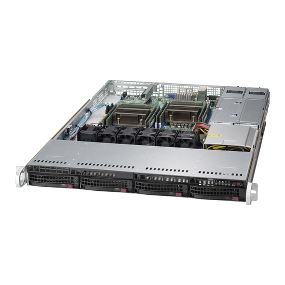
- Page 3 SC815 1U chassis. Installa- tion and maintenance should be performed by experienced technicians only. Supermicro’s SC815 1U chassis features a unique and highly-optimized design for dual-core Xeon platforms. The chassis is equipped with a 710W, 700W, 650W, 560W, or 450W high-efficiency power supply for superb power savings.
-
Page 4: Manual Organization
SC815 Chassis Manual Manual Organization Chapter 1: Introduction The first chapter provides a checklist of the main components included with this chassis and describes the main features of the SC815 chassis. This chapter also includes contact information. Chapter 2: System Safety This chapter lists warnings, precautions, and system safety. -
Page 5: Table Of Contents
CPU ......................... 1-3 Hard Drives ..................... 1-3 I/O Expansion slots ..................1-3 Peripheral Drives ..................... 1-3 Other Features ....................1-3 Contacting Supermicro ..................1-4 Returning Merchandise for Service ..............1-5 Chapter 2 System Safety Overview ......................2-1 Warnings and Precautions ................2-1 Preparing for Setup .................. - Page 6 SC815 Chassis Manual SCSI Drives ..................... 4-5 Power Supply LEDs and Overheat Indicators ..........4-5 450W and 650W Power Supply ..............4-5 All Other Power Supplies ................4-6 Overheating ..................... 4-6 Chapter 5 Chassis Setup and Maintenance Overview ......................5-1 Installation Procedures ..................
- Page 7 Preface Appendix A SC815 Chassis Cables Appendix B SC815 Power Supply Specifications Appendix C BPN-SAS-815TQ Backplane Specifications Appendix D BPN-SCA-813S Backplane Specifications...
- Page 8 SC815 Chassis Manual Notes viii...
-
Page 9: Chapter 1 Introduction
Chapter 1 Introduction Overview Supermicro’s SC815 1U chassis features a unique and highly-optimized design. The chassis is equipped with high efficiency power supply. High performance fans provide ample optimized cooling for FB-DIMM memory modules and 4 hot-swap drive bays offer maximum storage capacity in a 1U form factor. - Page 10 4x SAS / 1x FF 560W • SC815TQ-560CV / SC815TQ-560CB Xeon SATA DP Dual-core 4x U320 1x FF, 1x LF 560W • SC815S-560V / SC815S-560B Xeon SCSI DP Dual-core 4x U320 1x FF 560W • SC815S-560CV / SC815S-560CB Xeon SCSI UP Dual-core...
-
Page 11: Chassis Features
Chapter 1: Introduction Chassis Features The SC815 1U high performance chassis includes the following features: The SC815 Chassis supports a DP or UP Dual-core Xeon processor. Please refer to the motherboard specifications pages on our website for updates on supported processors. -
Page 12: Contacting Supermicro
Super Micro Computer, Inc. 980 Rock Ave. San Jose, CA 95131 U.S.A. Tel: +1 (408) 503-8000 Fax: +1 (408) 503-8008 Email: marketing@supermicro.com (General Information) support@supermicro.com (Technical Support) Web Site: www.supermicro.com Europe Address: Super Micro Computer B.V. Het Sterrenbeeld 28, 5215 ML... -
Page 13: Returning Merchandise For Service
For faster service, RMA authorizations may be requested online (http://www. supermicro.com/support/rma/). Whenever possible, repack the chassis in the original Supermicro carton, using the original packaging material. If these are no longer available, be sure to pack the chassis securely, using packaging material to surround the chassis so that it does not shift within the carton and become damaged during shipping. - Page 14 SC815 Chassis Manual Notes...
-
Page 15: Chapter 2 System Safety
Chapter 2: System Safety Chapter 2 System Safety Overview This chapter provides a quick setup checklist to get your chassis up and running. Following the steps in order given should enable you to have your chassis setup and operational within a minimal amount of time. This quick set up assumes that you are an experienced technician, famailiar with common concepts and terminology. -
Page 16: Electrical Safety Precautions
SC815 Chassis Manual Electrical Safety Precautions Basic electrical safety precautions should be followed to protect yourself from harm and the SC815 from damage: • Be aware of the locations of the power on/off switch on the chassis as well as the room’s emergency power-off switch, disconnection switch or electrical outlet. -
Page 17: General Safety Precautions
Chapter 2: System Safety radiation exposure, do not open the enclosure or use the unit in any uncon- ventional way. General Safety Precautions • Keep the area around the chassis clean and free of clutter. • Place the chassis top cover and any system components that have been re- moved away from the system or on a table so that they won’t accidentally be stepped on. - Page 18 SC815 Chassis Manual • Touch a grounded metal object before removing any board from its antistatic bag. • Do not let components or PCBs come into contact with your clothing, which may retain a charge even if you are wearing a wrist strap. •...
-
Page 19: Chapter 3 Chassis Components
SAS/SATA or SCSI. For more information regarding compat- ible backplanes, view the appendices found at the end of this manual. In addition, visit our Web site for the latest information: http://www.supermicro.com. Fans The SC815 chassis accepts four system fans with an optional fifth fan. System fans for SC815 chassis are powered from the serverboard. -
Page 20: Power Supply
Supermicro Authorized Distributors / System Integrators / Resellers. A list of Supermicro Authorized Distributors / System Integrators /Reseller can be found at: http://www.supermicro.com. Click the Where... -
Page 21: Chapter 4 System Interface
Chapter 4: System Interface Chapter 4 System Interface Overview There are several LEDs on the control panel and on the drive carriers that provide system and component status. This chapter explains the meanings of all LED indi- cators and the appropriate responses that need to be taken. Figure 4-1. -
Page 22: Control Panel Buttons
SC815 Chassis Manual Control Panel Buttons The SC815 chassis includes two or three push-buttons located on the front panel: a reset button, a power on/off button, and a UID button • Reset: The reset button is used to reboot the system. •... -
Page 23: Control Panel Leds
Chapter 4: System Interface Control Panel LEDs The control panel located on the front of the SC815 chassis has up to five LEDs. These LEDs provide critical information related to different parts of the system. This section explains what each LED indicates when illuminated and any action that may be required. -
Page 24: Drive Carrier Leds
SC815 Chassis Manual • NIC2: Indicates network activity on GLAN2 when flashing. • NIC1: Indicates network activity on GLAN1 when flashing. • HDD: Indicates IDE channel activity. SAS/SATA drive, SCSI drive, and/or DVD- ROM drive activity when flashing. • Power: Indicates power is being supplied to the system's power supply units. This LED should normally be illuminated when the system is operating. -
Page 25: Scsi Drives
Chapter 4: System Interface connection to the SATA backplane enables this LED to blink on and off when that particular drive is being accessed. • Red: The red LED to indicate an SAS/SATA drive failure. If one of the SAS/SATA drives fail, you should be notified by your system management software. -
Page 26: All Other Power Supplies
Some backplanes allow the overheat temperature to be set at 45, 50, or 55 by changing a jumper setting. For more information, download the backplane user manual at www.supermicro.com. To access the manuals on the Website, click support, and then click the manuals link. - Page 27 Chapter 4: System Interface Check the routing of the cables and make sure all fans are present and oper- ating normally. Verify that the heatsinks are installed properly.
- Page 28 SC815 Chassis Manual Notes...
-
Page 29: Chapter 5 Chassis Setup And Maintenance
Chapter 5: Chassis Setup and Maintenance Chapter 5 Chassis Setup and Maintenance Overview This chapter covers the steps required to install components and perform mainte- nance on the chassis. The only tool you will need to install components and perform maintenance is a Phillips screwdriver. -
Page 30: Removing The Chassis Cover And Front Bezel
SC815 Chassis Manual Removing the Chassis Cover and Front Bezel Removing the Chassis Cover: Press the release tabs to remove the cover from the locked position. Press both tabs at the same time. Once the top cover is released from the locked position, slide the cover toward the rear of the chassis. -
Page 31: The Front Bezel
Chapter 5: Chassis Setup and Maintenance Front Bezel Release Knob Bezel pins Bezel Lock Figure 5-2: Removing the Front Bezel The Front Bezel If your system has an optional front bezel attached to the chassis, you must remove it to access the drive bays. A filter located within the bezel can be removed for cleaning or replacement. -
Page 32: Installing Hard Drives
SC815 Chassis Manual Installing Hard Drives Removing Hard Drive Trays from the Chassis 1. Press the release button on the drive tray. This extends the drive bay handle. 2. Use the handle to pull the drive out of the chassis. - Page 33 Chapter 5: Chassis Setup and Maintenance Figure 5-4: Chassis Drive Tray The drives are mounted in drive carriers to simplify their installation and removal from the chassis. These carriers also help promote proper airflow for the drive bays. Warning: Except for short periods of time (swapping hard drives), do not operate the server with the hard drives empty.
- Page 34 SC815 Chassis Manual Install a new drive into the carrier with the printed circuit board side facing down so that the mounting holes align with those in the carrier. Secure the hard drive by tightening all six (6) screws. Replace the drive tray into the chassis. Make sure the close the drive tray handle.
-
Page 35: Dvd And Floppy Drive Installation
Chapter 5: Chassis Setup and Maintenance DVD and Floppy Drive Installation Most SC815 chassis models include a DVD-ROM and space for an optional floppy drive. The DVD-ROM is usually pre-installed. Installing or Replacing a DVD-ROM or Floppy Drive Power down the system and if necessary, remove the server from the rack and the front bezel from the chassis. -
Page 36: Installation Step 4: Installing The Motherboard
SC815 Chassis Manual Installation Step 4: Installing the Motherboard Permanent Standoffs Optional Standoffs Figure 5-8: Chassis Standoffs Permanent and Optional Standoffs Standoffs prevent short circuits by securing space between the motherboard and the chassis surface. The SC815 chassis includes permanent standoffs in locations used by most motherboards. - Page 37 Chapter 5: Chassis Setup and Maintenance Installing the Motherboard: Review the documentation that came with your motherboard. Become famil- iar with component placement, requirements, and precautions. Disconnect the power supply and lay the chassis on a flat surface. Open the chassis cover. If necessary, remove the riser card.
-
Page 38: Expansion Card Setup
Note: You must use a riser card to install expansion cards to any SC815 chassis. Riser cards are sold separately. For the latest compatibility and performance information visit our website at: SC815-560C http://www.supermicro.com. C815-560C I/O Panel Lever I/O Panel... - Page 39 Chapter 5: Chassis Setup and Maintenance Riser Card Figure 5-11: Chassis with a Riser Card ("U" Models Only) Installing an Expansion Card Confirm that you have the correct riser card for your chassis model and the add-on card includes a standard bracket. Remove the chassis cover.
-
Page 40: Installing The Air Shroud
SC815 Chassis Manual Installing the Air Shroud Optional Flap Figure 5-11: Air Shroud Front (Fan Side) Air shrouds concentrate airflow to maximize fan efficiency. The SC815 chassis air shroud does not require screws to set up. Figure 5-12: Air Shroud without the Otional Flap 5-12... - Page 41 Chapter 5: Chassis Setup and Maintenance Installing the Air Shroud Remove the chassis cover. If your motherboard uses between 9 and 16 DIMMS, skip this step. If your motherboard uses 8 DIMMS, you must remove the optional flap. To do so: a.
-
Page 42: System Fans
SC815 Chassis Manual System Fans Figure 5-13: System Fan Four heavy duty fans provide cooling for the chassis. These fans circulate air through the chassis as a means of lowering the chassis' internal temperature. In models with counter-rotating fans, each fan unit is actually made up of two fans joined back-to-back, which rotate in opposite directions. - Page 43 Chapter 5: Chassis Setup and Maintenance Figure 5-14: Chassis Fans (shown with optional fan installed) The SC815 Chassis includes four pre-installed fans. One or two extra slots are available so that. additional fans may be added. Replacing a System Fan If necessary, open the chassis while the power is running to determine which fan has failed.
-
Page 44: Power Supply
If the power supply unit fails, the system will shut down and you will need to replace the unit. Replacement units can be ordered directly from Supermicro (see contact information in the Preface). As there is only one power supply unit in the SC815 Chassis, power must be completely removed from the server before removing and replacing the power supply unit for whatever reason. - Page 45 Chapter 5: Chassis Setup and Maintenance Release Tab Figure 5-15: Removing the Power Supply Replacing the Power Supply Power down the server and unplug the power cord. If your chassis includes a redundant power supply (at least two power modules), you can leave the server running and remove only one power supply.
- Page 46 SC815 Chassis Manual Notes 5-18...
-
Page 47: Chapter 6 Rack Installation
Chapter 6: Rack Installation Chapter 6 Rack Installation Overview This chapter provides a quick setup checklist to get your chassis up and running. Following these steps in the order given should enable you to have the system operational within a minimum amount of time. Unpacking the System You should inspect the box the chassis was shipped in and note if it was damaged in any way. -
Page 48: Rack Precautions
SC815 Chassis Manual Warnings and Precautions! Rack Precautions • Ensure that the leveling jacks on the bottom of the rack are fully extended to the floor with the full weight of the rack resting on them. • In single rack installation, stabilizers should be attached to the rack. •... -
Page 49: Rack Mounting Considerations
Chapter 6: Rack Installation Rack Mounting Considerations Ambient Operating Temperature If installed in a closed or multi-unit rack assembly, the ambient operating tempera- ture of the rack environment may be greater than the ambient temperature of the room. Therefore, consideration should be given to installing the equipment in an environment compatible with the manufacturer’s maximum rated ambient tempera- ture (Tmra). -
Page 50: Rack Mounting Instructions
SC815 Chassis Manual Rack Mounting Instructions This section provides information on installing the SC815 chassis into a rack unit with the rails provided. There are a variety of rack units on the market, which may mean the assembly procedure will differ slightly. You should also refer to the installation instructions that came with the rack unit you are using. -
Page 51: Inner Rail Extension
Chapter 6: Rack Installation Figure 6-2. Identifying the Sections of the Rack Rails (right side rail shown) Installing the I(nner Rails Place the inner rack extensions on the side of the chassis aligning the hooks of the chassis with the rail extension holes. Make sure the extension faces "outward"... - Page 52 SC815 Chassis Manual Secure to the Front of the Rack Secure to the Rear of the Rack Attach Outer Racks together Figure 6-3. Assembling the Outer Rails Installing the Outer Rails to the Rack Attach the short bracket to the outside of the long bracket. You must align the pins with the slides.
- Page 53 Chapter 6: Rack Installation SCALE 0.380 Figure 6-4. Installing the Outer Rails to the Server Rack...
- Page 54 SC815 Chassis Manual Figure 6-5. Installing the Rack Rails Installing the Chassis into a Rack Confirm that chassis includes the inner rails (A) and rail extensions (B). Also, confirm that the outer rails (C) are installed on the rack. Line chassis rails (A and B) with the front of the rack rails (C). Slide the chassis rails into the rack rails, keeping the pressure even on both sides (you may have to depress the locking tabs when inserting).
-
Page 55: Installing The Chassis Into A Telco Rack
Chapter 6: Rack Installation Installing the Chassis into a Telco rack If you are installing the SC815 chassis into a Telco type rack, follow the directions given on the previous pages for rack installation. The only difference in the installa- tion procedure will be the positioning of the rack brackets to the rack. - Page 56 SC815 Chassis Manual Notes 6-10...
- Page 57 This appendix lists supported cables for your chassis system. It only includes the most commonly used components and configurations. For more compatible cables, refer to the manufacturer of the motherboard you are using and our Web site at: www.supermicro.com. Cables Included with SC815TQ Chassis (SAS/ SATA)
- Page 58 SC815 Chassis Manual SC815TQ-R650 Part # Type Length Description Round 8 pin to 8 pin ribbon cable for CBL-0157L Ribbon 9" SGPIO. Cable Ribbon, 16 pin to 16 pin ribbon cable for CBL-0087 Round 20" control panel Cable Braid CBL-0139L Ribbon 50 cm IDE 80-Wire cable for DVD ROM...
- Page 59 Appendix A Cables Included with SC815S Chassis (SCSI) SC815S-700 Part # Type Length Description Round CBL-033L-U320 Ribbon 9" ULTRA 320 cable Cable Ribbon, 16 pin to 16 pin ribbon cable for CBL-0087 Round 20" control panel Cable Braid CBL-0139L Ribbon 50 cm IDE 80-Wire cable for DVD ROM Cable...
- Page 60 SC815 Chassis Manual Compatible Cables These cables are compatible with the SC815 Chassis. Alternate SAS/SATA Cables Some compatible motherboards have different connectors. If your motherboard has only one SAS connector that the SAS/SATA cables must share, use one of the following cables.
-
Page 61: Extending Power Cables
Appendix A Extending Power Cables Although Super Micro chassis are designed with to be efficient and cost-effective, some compatible motherboards have power connectors located in different areas. To use these motherboards you may have to extend the power cables to the mother boards. - Page 62 SC815 Chassis Manual Notes...
- Page 63 Appendix B Appendix B SC815 Power Supply Specifications This appendix lists power supply specifications for your chassis system. 650W/PDB 560W 710W/PDB 700W/PDB (Redun- 560W (C Models) dant) PWS- PWS-651- PWS-561- PWS-711-1R PWS-561-1H Part # 702A-IR 1H20 Rated 100 - 240V 100 - 240V 100 - 240V 100 - 240V...
- Page 64 SC815 Chassis Manual Notes...
- Page 65 Safety Information and Technical Specifications Appendix C BPN-SAS-815TQ Backplane Specifications To avoid personal injury and property damage, carefully follow all the safety steps listed below when accessing your system or handling the components. C-1 ESD Safety Guidelines Electric Static Discharge (ESD) can damage electronic components. To prevent dam- age to your system, it is important to handle it very carefully.
-
Page 66: Front Connectors
Safety Information and Technical Specifications Jumper Settings and Pin Definitions C-4 Front Connectors and Jumpers JTAG UPGRADE JP29:9071 RST JP18:BUZZER RESET JP40 JP42 JP51 UPER SAS815TQ JP29 JP18 JP33 REV 1.00 JP34 M9 M15 SIDEBAND +12V JP47 JP10 +12V +12V JP26 JP44 ACT IN... - Page 67 SC815 Chassis Manual C-5 Front Connector and Pin Definitions #1. Backplane Main Power Connectors Backplane Main Power The 4-pin connectors, designated JP10 provide 4-Pin Connector (JP10) power to the backplane. See the table on the Pin# Definition right for pin definitions. +12V 2 and 3 Ground...
- Page 68 Safety Information and Technical Specifications #6. Sideband Headers Sideband Headers (JP51) The sideband headers are designated JP51. Pin # Definition Pin # Definition For SES-2 to work properly, you must connect Backplane Controller an 8-pin sideband cable. See the table to the Addressing ID (SB6) (SB5)
- Page 69 SC815 Chassis Manual C-6 Front Jumper Locations and Pin Definitions JP29:9071 RST JP18:BUZZER RESET JP40 JP42 JP51 SAS815TQ JTAG UPGRADE JP29 UPER JP18 JP33 JP34 REV 1.00 M9 M15 SIDEBAND +12V JP47 JP10 +12V +12V JP26 JP44 ACT IN ACT0 ACT1 ACT2 ACT3 JP29:9071 RST...
-
Page 70: I2C And Sgpio Modes And Jumper Settings
Safety Information and Technical Specifications I2C and SGPIO Modes and Jumper Settings This backplane can utilize I2C or SGPIO. I2C is the default mode and can be used without making changes to your jumpers. The following information details which jumpers must be configured to use SGPIO mode or restore your backplane to I2C mode. - Page 71 SC815 Chassis Manual C-7 Rear Connectors and LED Indicators Rear SAS/SATA Connectors Rear Connector SAS Drive Connector Number Number SAS #0 SAS/SATA HDD #0 SAS #1 SAS/SATA HDD #1 SAS #2 SAS/SATA HDD #2 SAS #3 SAS/SATA HDD #3 Rear LED Indicators Rear Hard Drive Activity Failure LED...
- Page 72 Safety Information and Technical Specifications Appendix D BPN-SCA-813S Backplane Specifications To avoid personal injury and property damage, carefully follow all the safety steps listed below when accessing your system or handling the components. D-1 ESD Safety Guidelines Electric Static Discharge (ESD) can damage electronic components. To prevent dam- age to your system, it is important to handle it very carefully.
- Page 73 SC815 Chassis Manual D-3 An Important Note to Users • All images and layouts shown in this user's guide are based upon the latest PCB Revision available at the time of publishing. The card you have received may or may not look exactly the same as the graphics shown in this manual.
- Page 74 SC815 Chassis Manual Jumper Settings and Pin Definitions D-4 Front Connectors and Jumpers +12V LVD1 UPER SCA813S REV 1.03 JP17: BUZZER ENABLE JP17 ON: ENABLE +5V GND +12V +12V OFF: DISABLE Front Connectors #1. Backplane Main (4-Pin) PWR: JP10 #2. GEM 318 Chip #3.
- Page 75 Safety Information and Technical Specifications D-5 Front Connector and Pin Definitions #1. Backplane Main Power Connectors Backplane Main Power The 4-pin connector, designated JP10, provide 4-Pin Connector (JP10) power to the backplane. See the table on the Pin# Definition right for pin definitions. +12V 2 and 3 Ground...
- Page 76 SC815 Chassis Manual #4. Ultra 320 SCSI Connector (LVD1) Ultra320 SCSI Drive Connector Pin Definitions (J28) The Ultra 320 SCSI connector connects Pin# Definition Pin # Definition the backplane to the server mother- +DB (12) -DB (12) board. +DB (13) -DB (13) +DB (14) -DB (14)
-
Page 77: Explanation Of Jumpers
Safety Information and Technical Specifications D-6 Front Jumper Locations and Pin Definitions +12V SCA813S LVD1 UPER REV 1.03 JP17: BUZZER ENABLE JP17 ON: ENABLE +5V GND +12V +12V OFF: DISABLE Explanation of Jumpers Connector Pins To modify the operation of the backplane, jumpers can be used to choose between Jumper... - Page 78 SC815 Chassis Manual D-7 Rear Connectors and LED Indicators ACT0 ACT1 ACT2 FAIL0 FAIL2 FAIL1 SCA4 SCA2 Rear SCA Connectors Rear Connector SCA Drive Connector Number Number SCA #1 SCA HDD #0 SCA #3 SCA HDD #1 SCA #4 SCA HDD #2 SCA #2 SCA HDD #3 Rear LED Indicators...
- Page 79 Click “Next” twice, uncheck both “Floppy disk drives” and “CD-ROM drives”. Select “Specify a location,” and choose “Next”. Click on “Browse” and choose D drive or wherever Supermicro Setup CD is Choose “Qlogic” folder and click on “Open”. System will automatically detect the GEM318 chip and install the drive from this point on.
- Page 80 SC815 Chassis Manual Click on the Hardware tab and click on "Device Manager" to bring up the list of system devices. You may see one or two yellow question marks (?) that read QLogic GEM354 or GEM318 SCSI Processor Device. Right click on these, and choose to uninstall.
Need help?
Do you have a question about the SC815S-560B and is the answer not in the manual?
Questions and answers