Table of Contents
Advertisement
Quick Links
1.2 System Features
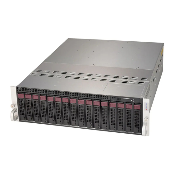
The CSE-938NH-R2K20BP2 is a 3U chassis that supports 16 front hot-swape drives and
eight rear hot-plug nodes.
Front View
1A
1B
2A
Feature
Description
Control Panels
Power buttons and status indicators; details on the next page
Storage Drives
Sixteen 3.5" drive bays, two for each computing node; drive carriers display status lights
Color
LED
Blue
Activity LED
Blue
Red
Red
Red
Status LED
Red
Red
Green
Amber
2B
3A
3B
4A
4B
Figure 1-1. System: Front View
System Features: Front
Drive Carrier LED Indicator
Blinking Pattern
Solid On
Blinking
Solid On
Blinking at 1 Hz
Blinking with two blinks and one
stop at 1 Hz
On for five seconds, then off
Blinking at 4 Hz
Solid On
Blinking at 1 Hz
10
Chapter 1: Introduction
Control Panel
5A
5B
6A
6B
7A
Behavior for Device
SAS/NVMe drive installed
I/O activity
Failure of drive with RSTe support
Rebuild drive with RSTe support
Hot spare for drive with RSTe support
(not supported in VMD mode)
Power on for drive with RSTe support
Identify drive with RSTe support
Safe to remove NVMe device (not
supported in VMD mode)
Attention state---do not remove NVMe
device (not supported in VMD mode)
7B
8A
8B
Advertisement
Table of Contents


Need help?
Do you have a question about the CSE-938NH-R2K20BP2 and is the answer not in the manual?
Questions and answers