Table of Contents
Advertisement
Advertisement
Table of Contents

Subscribe to Our Youtube Channel
Related Manuals for Datalogic Matrix 300


Summary of Contents for Datalogic Matrix 300
- Page 1 > Matrix 300™...
- Page 2 Matrix 300™ Reference Manual Ed.: 07/2014 © 2013 - 2014 Datalogic Automation S.r.l. ALL RIGHTS RESERVED. Protected to the fullest extent under U.S. and international laws. Copying, or altering of this document is prohibited without express written consent from Datalogic Automation S.r.l.
-
Page 3: Table Of Contents
RAPID CONFIGURATION CONTENTS REFERENCES ......................vi Conventions ......................... vi Reference Documentation ................... vi Support Through The Website ..................vi Patents ......................... vi COMPLIANCE ......................vii EMC Compliance ......................vii Power Supply ....................... vii CE Compliance ......................vii FCC Compliance ......................vii Laser Safety ........................ - Page 4 FOV Calculation ......................80 6.1.1 Global FOV Diagrams for 6 mm Manual Adjustable Focus Models ......81 6.1.2 Matrix 300 4x2 9 mm Liquid Lens Global FOV Diagrams ........... 82 Reading Diagrams ...................... 83 6.2.1 Pre-Configured .INI Files .................... 83 Matrix 300 4x1 (6 mm models) ...................
- Page 5 RAPID CONFIGURATION 7.5.8 Region Of Interest Windowing .................. 123 7.5.9 Direct Part Marking Applications ................124 Image Capture and Decoding ................... 129 Statistics ........................129 MAINTENANCE ....................... 130 Cleaning ........................130 TROUBLESHOOTING ..................... 131 General Guidelines ....................131 TECHNICAL FEATURES ..................134 ALTERNATIVE CONNECTIONS ................
-
Page 6: References
Mode Programming, Matrix SW Parameter Guide, Matrix Code Quality Verifier Solution provided as supplementary documentation on Mini-DVD. SUPPORT THROUGH THE WEBSITE Datalogic provides several services as well as technical support through its website. Log on to www.datalogic.com and click on the Industrial Automation links for further information: ... -
Page 7: Compliance
FCC COMPLIANCE Modifications or changes to this equipment without the expressed written approval of Datalogic could void the authority to use the equipment. This device complies with PART 15 of the FCC Rules. Operation is subject to the following two conditions: (1) This device may not cause harmful interference, and (2) this device must accept any interference received, including interference which may cause undesired operation. -
Page 8: Laser Safety
LASER SAFETY The Matrix 300™ internal illuminators contain two aiming Laser LEDs used to position the reader. This product conforms to the applicable requirements of IEC 60825-1 and complies with 21 CFR 1040.10 except for deviations pursuant to Laser Notice N° 50, date June 24, 2007. This product is classified as a Class 2 laser product according to IEC 60825-1 regulations. -
Page 9: Handling
RAPID CONFIGURATION HANDLING The Matrix 300™ is designed to be used in an industrial environment and is built to withstand vibration and shock when correctly installed, however it is also a precision product and therefore before and during installation it must be handled correctly to avoid damage. - Page 10 do not weld the reader into position which can cause electrostatic, heat or reading window damage. do not spray paint near the reader which can cause reading window damage.
-
Page 11: General View
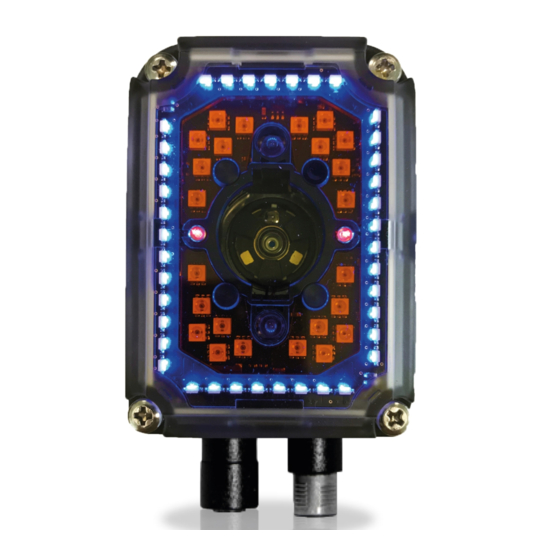
RAPID CONFIGURATION GENERAL VIEW Matrix 300™ Liquid Lens Models Figure A Connector block rotates to 90° position Power - Serial Interfaces - I/O Connector Device Class and Warning Labels Ethernet Connector Bracket Mounting Holes (4) No Read LED (red) Good Read LED (green) - Page 12 Matrix 300™ Fixed Lens Models Figure B Connector block rotates to 90° position Internal Illuminator Device Class and Warning Labels Power - Serial Interfaces - I/O Connector Bracket Mounting Holes (4) Good Read LED (green) Ethernet Connector Lens Cover No Read LED (red) HMI X-PRESS™...
-
Page 13: Rapid Configuration
External Trigger (photoelectric sensor) when the object enters its reading zone. PG-6000 Host CAB-DSxx Matrix 300™ Main Serial Interface (RS232 or RS485/422 Full-Duplex) External Trigger (for One Shot or Phase Mode) I/O, Aux Figure 1 – Matrix 300™ in Stand Alone Layout... - Page 14 MATRIX 300™ REFERENCE MANUAL CBX100/CBX500 Pinout for Matrix 300™ The table below gives the pinout of the CBX100/CBX500 terminal block connectors. Use this pinout when the Matrix 300™ reader is connected by means of the CBX100/CBX500: CBX100/500 Terminal Block Connectors Input Power...
-
Page 15: Step 2 - Mount And Position The Reader
RAPID CONFIGURATION STEP 2 – MOUNT AND POSITION THE READER 1. To mount the Matrix 300™, use the mounting brackets to obtain the most suitable position for the reader. The most common mounting configuration is shown in the figure below. -
Page 16: Step 3 - Aim And Autofocus The Reader
Aim LED will stop blinking and Matrix 300™ emits 3 high pitched beeps. If the Autofocus cannot be reached after a timeout of about 3 (three) minutes Matrix 300™ will exit without saving the parameters to memory, the Aim LED will stop blinking and in this case Matrix 300™... -
Page 17: Step 4 - X-Press™ Configuration
RAPID CONFIGURATION (Fixed Lens Models only) The Matrix 300™ fixed lens models are factory focused to a precise Reading Distance. If this distance is compatible with your application you can use the X-PRESS™ Interface to install the reader, if not, use the VisiSet™ procedure described in step 6B. - Page 18 PRESS™ push button once. After a short delay the Learn procedure is cancelled. NOTE: If you have used this procedure to configure Matrix 300™ go to step Reset Reader to Factory Default (Optional) If it ever becomes necessary to reset the reader to the factory default values, you can perform this procedure by holding the X-PRESS™...
-
Page 19: Step 5 - Installing Visiset™ Configuration Program
RAPID CONFIGURATION STEP 5 – INSTALLING VISISET™ CONFIGURATION PROGRAM ™ VisiSet is a Datalogic reader configuration tool providing several important advantages: Setup Wizard for rapid configuration and new users; Defined configuration directly stored in the reader; Communication protocol independent from the physical interface allowing the reader to be considered as a remote object to be configured and monitored. -
Page 20: Step 6A - Using Setup Wizard For Liquid Lens Models
MATRIX 300™ REFERENCE MANUAL STEP 6A – USING SETUP WIZARD FOR LIQUID LENS MODELS NOTE: For Fixed Lens models go to Step 6B. The Setup Wizard option is advised for rapid configuration or for new users. It allows reader configuration in a few easy steps. - Page 21 RAPID CONFIGURATION The Read. Dist. value is not significant until the Autofocus procedure ends successfully. 4. Select a Calibration Mode choice and press the "Calibrate" button. The reader flashes once acquiring the image and auto determines the best exposure and gain settings. 5.
- Page 22 MATRIX 300™ REFERENCE MANUAL The reader starts the focus procedure and gives visual feedback in the Setup Wizard window. The Setup Result section of the Setup Wizard window reports the procedure progress (in percentage). At the end of the procedure the Reading Distance, PPI and FOV data are reported.
- Page 23 RAPID CONFIGURATION 8. Select a Saving Options choice and press the "Save" button. 9. Close the Setup Wizard. NOTE: If your application has been configured using the VisiSet™ Setup Wizard, your reader is ready. If necessary you can use VisiSet™ for advanced reader configuration.
-
Page 24: Step 6B - Using Setup Wizard For Fixed Lens Models
MATRIX 300™ REFERENCE MANUAL STEP 6B – USING SETUP WIZARD FOR FIXED LENS MODELS NOTE: For Liquid Lens models go to Step 6A. The Setup Wizard option is advised for rapid configuration or for new users. It allows reader configuration in a few easy steps. - Page 25 RAPID CONFIGURATION 4. Select a Calibration Mode choice and press the "Calibrate" button. The reader flashes once acquiring the image and auto determines the best exposure and gain settings. 5. Press the "Fine Focusing" button to activate the Focus procedure. The reader continuously acquires images and gives visual feedback on the focusing quality in the Focusing Tool window.
- Page 26 MATRIX 300™ REFERENCE MANUAL Rotate the Focusing screw on the side of the reader. The Current Focus Quality Bar (green) together with the vertical optimal focus line (green) increase together until the optimal focus is reached; the vertical optimal focus line stops.
- Page 27 Press the "Close" button to return to the Setup Wizard. 6. Press the "Code Setting" button. The Grade A Barcode Test Chart, allows image density calibration to be performed so that Matrix 300™ will function correctly and to the fullest extent of its capabilities.
- Page 28 MATRIX 300™ REFERENCE MANUAL 7. Now place a single application specific code in front of the reader (at the same reading distance) and repeat steps 3, and 4. Do not perform step 5 "Fine Focusing". 8. Select a Code Setting Mode choice and press the "Code Setting" button.
- Page 29 RAPID CONFIGURATION 9. Select a Saving Options choice and press the "Save" button. 10. Close the Setup Wizard. NOTE: If your application has been configured using the VisiSet™ Setup Wizard, your reader is ready. If necessary you can use VisiSet™ for advanced reader configuration.
-
Page 30: Step 7 - Test Mode
MATRIX 300™ REFERENCE MANUAL STEP 7 – TEST MODE Use a code suitable to your application to test the reading performance of the system. 1. Enter the Test function by pressing and holding the X-PRESS™ push button until the Test LED is on. -
Page 31: Advanced Reader Configuration
Alternative Layouts If you need to install an Ethernet network, ID-NET™ network, or Fieldbus network, refer to the Matrix 300™ Reference Manual. The reader can also be setup for alternative layouts by reading programming barcodes. See the "Setup Procedure Using Programming Barcodes" printable from the Mini-DVD. -
Page 32: Introduction
MATRIX 300™ REFERENCE MANUAL 2 INTRODUCTION 2.1 PRODUCT DESCRIPTION Matrix 300™ is a Datalogic industrial compact 2D imager designed and produced to be a high performance affordable solution for both linear and two-dimensional code reading applications. Matrix 300™ uses imaging technology and provides complete reading system functions by integrating image capturing, decoding and communicating in a single compact and versatile product. - Page 33 INTRODUCTION Standard Application Program A Standard Application Program is factory-loaded onto Matrix 300™. This program controls code reading, data formatting, serial port and Ethernet interfacing, and many other operating and control parameters. It is completely user configurable from a Laptop or PC using the dedicated configuration software program VisiSet™, provided on Mini-DVD with the reader.
- Page 34 MATRIX 300™ REFERENCE MANUAL Ease of Setup Quick installation without PC by using X-PRESS™ interface for easy and intuitive setup Laser pointers for aiming Automatic Imager calibration and Code Settings Calibration Tool to verify exact code positioning in the Field of View and to maximize the reading performance ...
-
Page 35: Indicators And Keypad Button
INTRODUCTION Industrial Strength Industrial compact 2D reader Rugged metal construction Sealed circular connectors IP67 protection class 50 °C max operating temperature Supply voltage ranges from 10 to 30 Vdc The reader is particularly suitable for industrial environments where protection against harsh external conditions is required. -
Page 36: Id-Net
MATRIX 300™ REFERENCE MANUAL In normal operating mode the colors and meaning of the five LEDs are illustrated in the following table: green LED indicates that the reader is ready to operate (Figure 13, 7) READY green LED confirms successful reading (Figure 13, 6) -
Page 37: How To Setup/Configure The Reader Network
INTRODUCTION ID-NET™ M/S Multidata: Multiple stations – single reader ID-NET™ interface allows connection of readers reading objects placed on independent conveyors. All readers are typically located far away from each other and they use a dedicated presence sensor. At the end of each reading phase, each reader transmits its own data message to the host. Thanks to ID-NET™, data collection among readers is accomplished at a high speed without the need of an external multiplexing device. - Page 38 MATRIX 300™ REFERENCE MANUAL 6. If necessary, set the ID-NET™ baudrate from the Reading System Layout > Device Network Setting > Network Baud Rate parameter, (500 kbs default). 7. Configure the other device parameters via VisiSet™ [Operating Mode, Calibration, Data Collection parameters, etc.].
-
Page 39: Id-Net™ Slave Management Through Master
INTRODUCTION The reader network is ready. 2.3.2 ID-NET™ Slave Management Through Master When an ID-NET™ layout has already been configured, it is possible to modify the configuration of any Slave from VisiSet through the Master. 1. Connect a PC equipped with VisiSet™ to the Main, or Auxiliary interface of the Master reader. - Page 40 MATRIX 300™ REFERENCE MANUAL CAUTION: If a wrong configuration is set or if the Slave Reading System Layout parameters are changed, the slave could lose the network connection.
-
Page 41: External Memory Backup And Restore Through Visiset
INTRODUCTION 2.4 EXTERNAL MEMORY BACKUP RESTORE THROUGH VISISET™ The "External Memory Backup" or "External Memory Restore" functions allow performing Complete Configuration and Environmental parameter storage for network and reading devices. Backup & Restore can be applied to any reader connected through a device having External Backup Memory, regardless of the reader's network configuration. - Page 42 MATRIX 300™ REFERENCE MANUAL The VisiSet™ Main window shows information as the backup procedure is performed and a message indicating successful completion. Restore To perform a Restore: 1. Select "External Memory Restore" from the VisiSet™ Device menu 2. You will be warned that the current device configuration(s) will be overwritten. Confirm by...
- Page 43 INTRODUCTION The VisiSet™ Main window shows information as the restore procedure is performed and a message indicating successful completion. Replacement The External Memory Restore function also provides easy and secure Single Device Replacement: 1. Remove the device to be replaced 2.
- Page 44 MATRIX 300™ REFERENCE MANUAL Erase To Erase any previous Backup: 1. Select "External Memory Erase" from the VisiSet™ Device menu 2. You will be warned that all device configurations in the current backup will be erased. Confirm by clicking Yes.
- Page 45 INTRODUCTION List To see a List of the current Backup: 1. Select "External Memory Read Backup" from the VisiSet™ Device menu. The VisiSet™ Main window shows a list of devices in the current Backup. The following is a list of possible error messages displayed on the VisiSet™ main window in case of an External Memory function failure: ...
-
Page 46: X-Press™ Human Machine Interface
MATRIX 300™ REFERENCE MANUAL 2.5 X-PRESS™ HUMAN MACHINE INTERFACE X-PRESS™ is the intuitive Human Machine Interface designed to improve ease of installation and maintenance. Status information is clearly presented by means of the five colored LEDs, whereas the single push button gives immediate access to the following relevant functions: ... - Page 47 Setup LED will stop blinking and Matrix 300™ emits 3 high pitched beeps. If the calibration cannot be reached after a timeout of about 5 (five) seconds Matrix 300™ will exit without saving the parameters to memory, the Setup LED will stop blinking and in this case...
-
Page 48: Diagnostic Indication
Matrix 300™ emits 3 high pitched beeps. If the autolearning cannot be reached after a timeout of about 3 (three) minutes, Matrix 300™ will exit without saving the parameters to memory, the Learn LED will stop blinking and in this case Matrix 300™... -
Page 49: Lighting System Notes
INTRODUCTION 2.6.1 Lighting System Notes The following table shows the Matrix 300™ lens/illuminator combinations. For more information see the Application Note on illuminator selection on the mini-DVD. Matrix 300 Models Internal Illuminators Model Lens Type LEDs Type Matrix 300 411-0xx... -
Page 50: Application Examples
Figure 15 - Unidose Flow-Pack with PDF417 Code Figure 16 - Overprinted Barcode Readable by Matrix 300™ also Through the Envelope Window Film Figure 17 - Barcode Printed on Curved Surface Readable by Matrix 300™ in spite of Image Optical Distortion... -
Page 51: Direct Part Marking
INTRODUCTION 2.8.3 Direct Part Marking Matrix 300™ is also very powerful in reading low-contrast direct part marked codes (see Figures 20, 21, and 22). Figure 18 - Dot Matrix Code Directly Marked on Metal Surface by Using Dot Peening Technology... -
Page 52: Laser Marking/Etching Technology
Figure 22 - Data Matrix Code Directly Marked on PCB Surface by Using Laser Etching Technology CAUTION: If application codes must be read which are produced by Laser Marking in real time, use Matrix 300™ models incorporating YAG Filters in order to avoid burning the CMOS sensor. -
Page 53: Installation
INSTALLATION 3 INSTALLATION 3.1 PACKAGE CONTENTS Verify that the Matrix 300™ reader and all the parts supplied with the equipment are present and intact when opening the packaging; the list of parts includes: Matrix 300™ reader Quick Reference Guide ... -
Page 54: Mechanical Dimensions
MATRIX 300™ REFERENCE MANUAL 3.2 MECHANICAL DIMENSIONS Matrix 300™ can be installed to operate in different positions. The twelve screw holes (M4 x 5) on the body of the reader are for mechanical fixture (Figure 24). The diagram below gives the overall dimensions of the reader and may be used for its installation. - Page 55 INSTALLATION 20.5 [0.81] [2.12] [1.69] [1.42] M4 n°4 Optical Axes Figure 25 - Overall Dimensions with Connector at 90°...
- Page 56 MATRIX 300™ REFERENCE MANUAL [1.85] M 4 N°5 17.7 [0.70] [1.42] Ø4.5 [Ø0.18] [0.18] 90° [1.85] [0.18] Ø8.2 [Ø0.32] Figure 26 - Mounting Bracket Overall Dimensions...
-
Page 57: Mounting And Positioning Matrix 300
INSTALLATION 3.3 MOUNTING AND POSITIONING MATRIX 300™ Using the Matrix 300™ mounting brackets you can obtain rotation on the various axes of the reader as shown in the diagram below: Pitch Tilt Figure 27 –Positioning with Mounting Bracket... - Page 58 The Pitch, Skew and Tilt angles are represented in Figure 28. Follow the suggestions below for the best orientation: Position the reader in order to avoid the direct reflection of the light emitted by the Matrix 300™ reader; it is advised to assure at least 10° for the Skew angle.
- Page 59 INSTALLATION Linear Barcode Reading 2D Code Reading Figure 29 - Tilt Angle Considerations See chp. 6 for FOV vs. Reading Distance considerations.
-
Page 60: Cbx Electrical Connections
All Matrix 300™ models can be connected to a CBX connection box through one of the available CAB-DSxx-S accessory cables. These accessory cables terminate in an M12 17- pin connector on the Matrix 300™ side and in a 25-pin male D-sub connector on the CBX side. -
Page 61: Power Supply
CBX connection box, verify the jumper positions in the CBX as indicated in its Installation Manual. 4.1 POWER SUPPLY Power requirements and conditions depend on the Matrix 300™ model: Standard or PoE (Power over Ethernet). 4.1.1 Standard Models... - Page 62 Midspan PSE device is not supported. Figure 32 – Matrix 300™ PoE PSE Endspan Alternative A Connections OK Figure 33 – Matrix 300™ PoE PSE Midspan Alternative A Connections OK Figure 34 – Matrix 300™ PoE PSE Endspan Alternative B Connections NOT SUPPORTED...
-
Page 63: Main Serial Interface
CBX ELECTRICAL CONNECTIONS Figure 35 – Matrix 300™ PoE PSE Midspan Alternative B Connections NOT SUPPORTED CAUTION: For Matrix 300™ PoE models, the internal Digital Output circuitry is not powered and supply power is not available to any Input/Output devices (Vdc=0). Only input device signals can be accepted directly on the M12 17-pin connector without power. -
Page 64: Rs232 Interface
IDLE Figure 37 - RS232 Control Signals If the RTS/CTS handshaking protocol is enabled, the Matrix 300™ activates the RTS output to indicate a message is to be transmitted. The receiving unit activates the CTS input to enable the transmission. -
Page 65: Rs485/422 Full-Duplex Interface
CBX ELECTRICAL CONNECTIONS 4.2.2 RS485/422 Full-Duplex Interface The RS485/422 full-duplex (5 wires + shield) interface is used for non-polled communication protocols in point-to-point connections over longer distances (max 1200 m / 3940 ft) than those acceptable for RS232 communications or in electrically noisy environments. The CBX pinout follows: CBX100/500 Function... -
Page 66: Id-Net™ Interface
1200 m 900 m 700 m * Application dependent, contact your Datalogic Automation representative for details. NOTE: The default ID-NET™ baudrate is 500 kbps. Lower ID-NET™ baudrates allow longer cable lengths. The baudrate is software configurable by authorized Datalogic Automation personnel only. -
Page 67: Id-Net™ Response Time
CBX ELECTRICAL CONNECTIONS 4.3.2 ID-NET™ Response Time The following figure shows the response time of the ID-NET™ network. This time is defined as the period between the Trigger activation and the beginning of data transmission to the Host. Max ID-NET™ Response Time 14 15 Number of Nodes 500 kbps... - Page 68 MATRIX 300™ REFERENCE MANUAL Figure 41 – ID-NET™ Network Connections with isolated power blocks...
- Page 69 CBX ELECTRICAL CONNECTIONS Figure 42 - ID-NET™ Network Connections with Common Power Branch Network...
- Page 70 MATRIX 300™ REFERENCE MANUAL Figure 43 – ID-NET™ Network Connections with Common Power Star Network...
-
Page 71: Id-Net™ Network Termination
CBX ELECTRICAL CONNECTIONS 4.3.3 ID-NET™ Network Termination The network must be properly terminated in the first and last reader of the network. This is done by setting the ID-NET™ Termination Resistance Switch in the CBX100/500 to ON. 4.4 AUXILIARY RS232 INTERFACE The RS232 auxiliary interface is available for Point-to-Point, Pass Through or Master/Slave connections. -
Page 72: Inputs
MATRIX 300™ REFERENCE MANUAL 4.5 INPUTS There are two optocoupled polarity insensitive inputs available on the reader: Input 1 (External Trigger) and Input 2, a generic input: The External Trigger can be used in One Shot Mode or in Phase Mode. Its main functions are: ... - Page 73 Input Device on the +V/-V spring clamps, and does not pass through the Power Switch (ON/OFF) inside the CBX. Disconnect the power supply when working inside the CBX. PH-1 Photocell (PNP) (brown) (black) (blue) Figure 46 – PH-1 External Trigger Using Matrix 300™ Power NPN Photocell Power to Input Photocell Signal Photocell Reference Figure 47 - NPN External Trigger Using Matrix 300™...
- Page 74 Input 2 B (polarity insensitive) Power Reference - Inputs INPUT 2 CONNECTIONS USING MATRIX 300™ POWER CAUTION: Power from the Vdc/GND spring clamps is available directly to the Input Device on the +V/-V spring clamps, and does not pass through the Power Switch (ON/OFF) inside the CBX.
- Page 75 CBX ELECTRICAL CONNECTIONS Input Device Pulled up to External Input Device Power Input Signal Figure 51 - NPN Input 2 Using External Power INPUT 3 CONNECTIONS (CBX500 Only) RESERVED Figure 52 - Input 3 Using External Power CAUTION: Do not connect to I3A or I34B signals, they are reserved.
-
Page 76: Outputs
MATRIX 300™ REFERENCE MANUAL 4.6 OUTPUTS CAUTION: When Outputs 1 and 2 are connected through the CBX connection box, they become opto-isolated and polarity sensitive and acquire the electrical characteristics listed below. To function correctly, they require setting the Output Type configuration parameters to NPN for the respective output in. - Page 77 Output device Signal Output device Signal Output device Output device Reference Reference Figure 53 - PNP/Open Emitter Output Using MATRIX 300™ Power Output 1 Device Output 2 Device Power to Power to Output device Output device Output device Output device...
- Page 78 Output 3 is not opto-isolated but can be assigned to the same events. By default it is not assigned to any event. The CBX500 must be used to connect this output. OUTPUT 3 CONNECTIONS USING MATRIX 300™ POWER (CBX500 Only) Power to...
-
Page 79: On-Board Ethernet Interface
The on-board Ethernet Interface can be used for TCP/IP communication with a remote or local host computer by connecting the reader to either a LAN or directly to a host PC. There is no need to use a crossover adapter since Matrix 300™ incorporates an auto-cross function. -
Page 80: Typical Layouts
MATRIX 300™ REFERENCE MANUAL 5 TYPICAL LAYOUTS The following typical layouts refer to system hardware configurations. However, they also require the correct setup of the software configuration parameters. Dotted lines in the figures refer to optional hardware configurations within the particular layout. - Page 81 When One Shot or Phase Mode operating mode is used, the reader can be activated by an External Trigger (for example a pulse from a photoelectric sensor) when the object enters its reading zone. Power CBX500 CAB-DSxx Matrix 300™ BM2x0 TCP/IP Ethernet Interface Auxiliary Serial Interface (Local Echo) (RS232) ...
- Page 82 MATRIX 300™ REFERENCE MANUAL In this layout a single reader functions as a Slave node on a Fieldbus network. The data is transmitted to the Host through an accessory Fieldbus interface board installed inside the CBX500 connection box. Reader configuration can be accomplished through the Auxiliary interface using the VisiSet™...
-
Page 83: Id-Net™ Synchronized Network
TYPICAL LAYOUTS 5.2 ID-NET™ SYNCHRONIZED NETWORK The ID-NET™ connection is used to collect data from several readers to build a multi-point or a multi-sided reading system; there can be one master and up to 31 slaves connected together. The slave readers are connected together using the ID-NET™ interface. Every slave reader must have an ID-NET™... - Page 84 BA400 Ext. Power BA500 Trigger BA300 Service CBX500 Main CAB-AUX03 Figure 63 - ID-NET™ Synchronized Layout Matrix 300™ Master with CBX500 + Matrix 300™ Slaves with QL150 CAB-AUX03 CAB-AUX03 CBL-1496 ID-NET QL300 ID-NET™ QL150 QL150 Terminator CBL-1480-xx...
- Page 85 TYPICAL LAYOUTS The same configuration can be made to a Host using a TCP/IP Ethernet interface. In this case the Master is connected to a CBX500 with BM200/210 Host Interface Module installed. The TCP/IP Ethernet, auxiliary, and ID-NET™ interfaces are connected as shown in the figure below.
-
Page 86: Id-Net™ Multidata Network
MATRIX 300™ REFERENCE MANUAL 5.3 ID-NET™ MULTIDATA NETWORK For a Master/Slave Multidata layout each reader has its own reading phase independent from the others; each single message is sent from the master reader to the Host computer. Master Slave#1 Slave#n... - Page 87 TYPICAL LAYOUTS The same configuration can be made to a Host using a TCP/IP Ethernet interface. In this case the Master is connected to a CBX500 with BM200/210 Host Interface Module installed. The TCP/IP Ethernet, auxiliary, and ID-NET™ interfaces are connected as shown in the figure below.
- Page 88 MATRIX 300™ REFERENCE MANUAL Alternatively, the Master reader can communicate to the Host as a Slave node on a Fieldbus network. This requires using an accessory Fieldbus interface board installed inside the CBX500 connection box. System configuration can be accomplished through the Auxiliary interface of each individual reader (internal CBX500 9-pin connector) using the VisiSet™...
-
Page 89: Pass-Through
(Master and Slaves) to accept input on the Auxiliary interface, for example to connect a device such as a hand-held reader for manual code reading capability. Each Matrix 300™ transmits its own messages plus any messages received by its Auxiliary interface onto the ID-NET™ interface. The Master passes all messages to the Host. -
Page 90: Ethernet Connection
VisiSet™. For further details, see the Ethernet Folder in the VisiSet™ Help On Line. In a Point-to-Point layout the reader is connected to a local host by using a CAB-ETH-M0x cable. There is no need to use a crossover adapter since Matrix 300™ incorporates an autocross function. - Page 91 TYPICAL LAYOUTS When using a Local Area Network (LAN), one or more Matrix 300s can be connected to the network by using CAB-ETH-M0x cables: Matrix 300™ Power Host NETWORK Ethernet Interface Auxiliary Serial Interface (Local Echo) (RS232) ...
-
Page 92: Reading Features
Figure 74 – Reading Distance References Example: The FOV for a Matrix 300 412-0xx at a reading distance of 200 mm is: = 2 [(200 mm + 14 mm) tan (40°/2)] 156 mm = 2 [(200 mm + 14 mm) tan (32°/2)] 123 mm NOTE: The following diagrams are given for typical performance at 25°C... -
Page 93: Global Fov Diagrams For 6 Mm Manual Adjustable Focus Models
READING FEATURES 6.1.1 Global FOV Diagrams for 6 mm Manual Adjustable Focus Models The following diagrams show the maximum obtainable Field of View for 1D and 2D codes using Processing Mode = Advanced Code Setting. Depending on the code resolution, symbology, and number of characters in the code, the Reading Area can be different from the FOV. -
Page 94: Matrix 300 4X2 9 Mm Liquid Lens Global Fov Diagrams
MATRIX 300™ REFERENCE MANUAL 6.1.2 Matrix 300 4x2 9 mm Liquid Lens Global FOV Diagrams The following diagrams show the maximum obtainable Field of View for 1D and 2D codes using Processing Mode = Advanced Code Setting. Depending on the code resolution, symbology, and number of characters in the code, the Reading Area can be different from the FOV. -
Page 95: Reading Diagrams
Data Matrix ECC 200 (2D code) from the Test Charts provided with the reader. Testing should be performed with the actual Matrix 300™ using application codes in order to evaluate whether maximizing application performance requires adjustments to the HW/SW configuration with respect to the Reference Conditions given under each diagram. -
Page 96: Matrix 300 4X1 (6 Mm Models)
MATRIX 300™ REFERENCE MANUAL 6.3 MATRIX 300 4X1 (6 MM MODELS) 6.3.1 1D (Linear) Codes Code 128 0.12 mm (5 mils) -1.5 Reading Distance CONDITIONS: Hardware Settings Code Symbology Code 128 Code Resolution 0.12 mm (5 mils) Tilt Angle 0°... - Page 97 READING FEATURES Code 128 0.25 mm (10 mils) Reading Distance CONDITIONS: Hardware Settings Code Symbology Code 128 Code Resolution 0.25 mm (10 mils) Tilt Angle 0° Skew Angle 15° Focusing Distance (mm) Software Parameters 411-xxx RED Wide Exposure Time (µs) Gain Illuminator Lighting Mode Very High Power Strobed...
- Page 98 MATRIX 300™ REFERENCE MANUAL Code 128 0.30 mm (12 mils) Reading Distance CONDITIONS: Hardware Settings Code Symbology Code 128 Code Resolution 0.30 mm (12 mils) Tilt Angle 0° Skew Angle 15° Focusing Distance (mm) Software Parameters 411-xxx RED Wide Exposure Time (µs)
- Page 99 READING FEATURES Code 128 0.33 mm (13 mils) Reading Distance CONDITIONS: Hardware Settings Code Symbology Code 128 Code Resolution 0.33 mm (13 mils) Tilt Angle 0° Skew Angle 15° Focusing Distance (mm) Software Parameters 411-xxx RED Wide Exposure Time (µs) Gain Illuminator Lighting Mode Very High Power Strobed...
- Page 100 MATRIX 300™ REFERENCE MANUAL Code 128 0.38 mm (15 mils) Reading Distance CONDITIONS: Hardware Settings Code Symbology Code 128 Code Resolution 0.38 mm (15 mils) Tilt Angle 0° Skew Angle 15° Focusing Distance (mm) Software Parameters 411-xxx RED Wide Exposure Time (µs)
- Page 101 READING FEATURES Code 128 0.50 mm (20 mils) Reading Distance CONDITIONS: Hardware Settings Code Symbology Code 128 Code Resolution 0.50 mm (20 mils) Tilt Angle 0° Skew Angle 15° Focusing Distance (mm) Software Parameters 411-xxx RED Wide Exposure Time (µs) Gain Illuminator Lighting Mode Very High Power Strobed...
-
Page 102: Bi-Dimensional) Codes
MATRIX 300™ REFERENCE MANUAL 6.3.2 2D (Bi-dimensional) Codes Data Matrix 0.19 mm (7.5 mils) Horizontal Max FOV Reading Width Reading Distance Max FOV +0.6 -0.6 Due to the "fisheye" effect of the wide angle 6 mm lens, the reading area for higher resolution codes is limited to the central zone of the Vertical Field of View. - Page 103 READING FEATURES Data Matrix 0.25 mm (10 mils) Horizontal Max FOV Reading Width Reading Distance Max FOV +0.8 -0.8 Due to the "fisheye" effect of the wide angle 6 mm lens, the reading area for higher resolution codes is limited to the central zone -1.5 of the Vertical Field of View.
- Page 104 MATRIX 300™ REFERENCE MANUAL Data Matrix 0.38 mm (15 mils) Reading Distance CONDITIONS: Hardware Settings Code Symbology Data Matrix ECC 200 Code Resolution 0.38 mm (15 mils) Tilt Angle 45° Skew Angle 10° Focusing Distance (mm) Software Parameters 411-xxx RED Wide Exposure Time (µs)
-
Page 105: Matrix 300 4X2 (9 Mm Models)
READING FEATURES 6.4 MATRIX 300 4X2 (9 MM MODELS) 6.4.1 1D (Linear) Codes Code 128 0.25 mm (10 mils) Reading Distance CONDITIONS: Hardware Settings Code Symbology Code 128 Code Resolution 0.25 mm (10 mils) Tilt Angle 45° Skew Angle 15°... - Page 106 MATRIX 300™ REFERENCE MANUAL Code 128 0.30 mm (12 mils) Reading Distance CONDITIONS: Hardware Settings Code Symbology Code 128 Code Resolution 0.30 mm (12 mils) Tilt Angle 45° Skew Angle 15° Software Parameters Reading Distance (mm) 412-xxx RED Wide Exposure Time (µs)
- Page 107 READING FEATURES Code 128 0.33 mm (13 mils) Reading Distance CONDITIONS: Hardware Settings Code Symbology Code 128 Code Resolution 0.33 mm (13 mils) Tilt Angle 45° Skew Angle 15° Software Parameters Reading Distance (mm) 412-xxx RED Wide Exposure Time (µs) 3300 Gain Illuminator Lighting Mode...
- Page 108 MATRIX 300™ REFERENCE MANUAL Code 128 0.38 mm (15 mils) Reading Distance CONDITIONS: Hardware Settings Code Symbology Code 128 Code Resolution 0.38 mm (15 mils) Tilt Angle 45° Skew Angle 15° Software Parameters Reading Distance (mm) 412-xxx RED Wide Exposure Time (µs)
-
Page 109: Bi-Dimensional) Codes
READING FEATURES 6.4.2 2D (Bi-dimensional) Codes Data Matrix 0.13 mm (5 mils) -0.5 -1.5 Reading Distance CONDITIONS: Hardware Settings Code Symbology Data Matrix ECC 200 Code Resolution 0.13 mm (5 mils) Tilt Angle 45° Skew Angle 20° Software Parameters Reading Distance (mm) 412-xxx RED Wide Exposure Time (µs) Gain... - Page 110 MATRIX 300™ REFERENCE MANUAL Data Matrix 0.19 mm (7.5 mils) Reading Distance CONDITIONS: Hardware Settings Code Symbology Data Matrix ECC 200 Code Resolution 0.19 mm (7.5 mils) Tilt Angle 45° Skew Angle 15° Software Parameters Reading Distance (mm) 412-xxx RED Wide Exposure Time (µs)
- Page 111 READING FEATURES Data Matrix 0.25 mm (10 mils) Reading Distance CONDITIONS: Hardware Settings Code Symbology Data Matrix ECC 200 Code Resolution 0.25 mm (10 mils) Tilt Angle 45° Skew Angle 15° Software Parameters Reading Distance (mm) 412-xxx RED Wide Exposure Time (µs) Gain Illuminator Lighting Mode Very High Power Strobed...
- Page 112 MATRIX 300™ REFERENCE MANUAL Data Matrix 0.38 mm (15 mils) Reading Distance CONDITIONS: Hardware Settings Code Symbology Data Matrix ECC 200 Code Resolution 0.38 mm (15 mils) Tilt Angle 45° Skew Angle 15° Software Parameters Reading Distance (mm) 412-xxx RED Wide Exposure Time (µs)
-
Page 113: Maximum Line Speed And Exposure Time Calculations
The maximum (theoretical) line speed LS can be calculated as follows: X / T = LS exp (max) (max) Example: A Matrix 300™ using: Internal Lighting Mode = Very High Power Strobe Exposure Time (x1 s) = 100 (100 Code Resolution (X) = 0.254 mm (10 mils) - Page 114 MATRIX 300™ REFERENCE MANUAL and LS are represented in the graph below as the curved line for X (code exp (max) (max) resolution). Values above the curve result in blurring. In practice, the application values are somewhere below the theoretical line, (in the green area), due to environmental and other conditions.
-
Page 115: Software Configuration
SOFTWARE CONFIGURATION 7 SOFTWARE CONFIGURATION Software configuration of your Matrix 300™ for static reading or simple code reading applications can be accomplished by the Rapid Configuration procedure using the X-PRESS™ HMI (which requires no external configuration program) or by using the VisiSet™... -
Page 116: Startup
After completing the mechanical and electrical connections to Matrix 300™, you can begin software configuration as follows: 1. Power on the Matrix 300™ reader. Wait for the reader startup. The system bootstrap requires a few seconds to be completed. The reader automatically enters Run Mode. -
Page 117: Visiset™ Options
SOFTWARE CONFIGURATION 7.3.1 VisiSet™ Options The Options item from the VisiSet™ menu (see Figure 75) presents a window allowing you to configure: the logging function (Log) VisiSet™ window properties (Environment) VisiSet™ communication channel (Communication) Figure 76 - Options - Log Figure 77 - Options - Environment... - Page 118 MATRIX 300™ REFERENCE MANUAL Figure 78 - Options – Communication: Serial Port Figure 79 - Options – Communication: Ethernet...
-
Page 119: Ethernet Configuration (Static Ip Addressing)
SOFTWARE CONFIGURATION 7.4 ETHERNET CONFIGURATION (STATIC IP ADDRESSING) If you want to connect to VisiSet™ using Ethernet then follow the procedure below. In order to find the reader using the VisiSet™ Look For Devices On Network tool, the reader and VisiSet™ must be on the same network (not through a sub-network or router). -
Page 120: Configuration
MATRIX 300™ REFERENCE MANUAL 7.5 CONFIGURATION Once connected to Matrix 300™ as described in par. 7.3 or 7.4, you can modify the configuration parameters as follows: 1. Press the Calibration Tool button from the Main Menu. Matrix 300™ will download its permanent memory configuration parameters with the default values (if it is the first time) to VisiSet™. -
Page 121: Edit Reader Parameters
SOFTWARE CONFIGURATION 7.5.1 Edit Reader Parameters The Parameter Setup window displays the configuration parameters grouped in a series of folders. Each parameter can be modified by selecting a different item from the prescribed list in the box, or by typing new values directly into the parameter box. By right clicking the mouse when positioned over the name of a specific Parameter or Group, a pop-up menu appears allowing you to directly manage that particular parameter or group. - Page 122 Allows configuring the device according to the desired layout: Standalone or ID-NET™ WebSentinel Enables the Ethernet WebSentinel Agent for communication with the Datalogic WebSentinel™ plant array monitor. Ethernet Sets the parameters related to the on board Ethernet interface and to its communication channels. Supports application protocols: TCP/IP, EtherNet/IP, Profinet IO and Modbus TCP ...
-
Page 123: Send Configuration Options
SOFTWARE CONFIGURATION When all the configuration parameters are set correctly, save them to the Matrix 300™ reader by pressing the Send button. See Figure 80. For successive configuration of other readers or for backup/archive copies, it is possible to save the configuration onto your PC by selecting the Save Configuration File option from the File menu. - Page 124 MATRIX 300™ REFERENCE MANUAL Environmental Parameters regard the device Identity and Position in a Network (ID-NET™, Ethernet, Fieldbus) and are not influenced by the "Send Default Configuration" and "Send Configuration" commands. This allows individual devices to be configured differently without affecting their recognized position in the network.
- Page 125 SOFTWARE CONFIGURATION HOST INTERFACE - Host Interface Type CBX ETHERNET SYSTEM (CBX with Host Interface Modules) - Status - DHCP Client - IP Address - Subnet Mask - Gateway Address PROFIBUS - Node Address DEVICENET - Node Address ETHERNET-IP - IP Addressing Mode - IP Address - Subnet Mask - Gateway Address...
- Page 126 MATRIX 300™ REFERENCE MANUAL For device replacement it is necessary to send the previously saved configuration (both Configuration and Environmental parameters) to the new device. To do this select "Send Configuration with Options" from the Device Menu and check the Environmental Parameters...
-
Page 127: Calibration
Parameter Setup window: Figure 81 - Calibration OK This tool provides a "real-time" image display while Matrix 300™ is reading. It also gives immediate results on the performance of the installed Matrix 300™ reader. If Self Tuning is enabled, the Calibration Tool window indicates the region where the calibration algorithm is performed: it is within the central box delimited by four red dots. - Page 128 MATRIX 300™ REFERENCE MANUAL The Parameter Setup window works in Interactive Mode in order to cause each parameter setting to be immediately effective. NOTE: If you want to save the temporary configuration to permanent memory, you must first close the Calibration Tool window. Then, you must disable the Interactive Mode and select the Permanent Memory option from the Send Configuration item in the Device menu.
- Page 129 SOFTWARE CONFIGURATION Over-exposure: To correct this result it is recommended to change the following parameters in their order of appearance: 1. decrease the Gain 2. decrease the Exposure Time Figure 83 - Example Over Exposure: Too Light...
-
Page 130: Multi Image Acquisition Settings
MATRIX 300™ REFERENCE MANUAL Moving code out of the Field of View: To correct this result and have the code completely visible in F.O.V., it is possible to follow one or both the procedures listed below: reposition the reader ... -
Page 131: Extending Dof Using Standard Acquisition Group (Cycle All In Same Phase)
SOFTWARE CONFIGURATION 7.5.5 Extending DOF Using Standard Acquisition Group (Cycle All In Same Phase) Multiple Image Acquisition Settings assigned to the same Acquisition Group (Standard), can be configured and enabled to extend the reader's depth of field. During each reading phase, decoding will be attempted by applying each enabled Image Acquisition Setting (cyclically). -
Page 132: Extending Dof Using Alternative Acquisition Group (Input Select)
MATRIX 300™ REFERENCE MANUAL 7.5.6 Extending DOF Using Alternative Acquisition Group (Input Select) NOTE: Do not use Interactive mode in VisiSet™ to set this feature. Multiple Image Acquisition Settings assigned to different Acquisition Groups (Standard and Alternative) can be configured and enabled to extend the reader's depth of field. The specific Acquisition Group (Standard or Alternative) is selected prior to the reading phase so that only the correct group setting will be applied to the entire reading phase. - Page 133 SOFTWARE CONFIGURATION Ext. Trigger Proximity Sensor on Input 2 Figure 85 - Example Extending DOF Using Alternative Acquisition Group Since many factors and parameters contribute to maximizing the reading process, it is suggested to use the VisiSet™ Standard Setup Wizard to set the different acquisitions settings.
-
Page 134: Run Time Self Tuning (Rtst)
These dynamic settings will be used instead of the static settings saved in memory. For more details see the Matrix 300™ Help On-Line. Self Tuning Image Processing In the Image Processing parameter setup menu, the Self Tuning parameters manage the Image Processing and Symbology related parameters. -
Page 135: Region Of Interest Windowing
The Top, Bottom, Left and Right parameters allow to precisely define the image window to be processed, visualized and saved. In all Matrix 300™ models the frame rate is dependent on the number of lines (or rows) in the defined window. -
Page 136: Direct Part Marking Applications
MATRIX 300™ REFERENCE MANUAL 7.5.9 Direct Part Marking Applications Decoding Method: Direct Marking For Data Matrix codes the Decoding Method parameter selects the decoding algorithm according to the printing/marking technique used to create the symbol and on the overall printing/marking quality. The Direct Marking selection improves the decode rate for low quality Direct Part Mark codes and in general for Direct Part Mark codes with dot peening type module shapes. - Page 137 SOFTWARE CONFIGURATION Image Filter Sets the filter to be applied to the image before being processed. This parameter can be used to successfully decode particular ink-spread printed codes (ex. Direct part mark codes). A different filter can be applied to each Image Acquisition Setting. The Erode Filter enlarges the image dark zones to increase readability.
- Page 138 MATRIX 300™ REFERENCE MANUAL The Open filter eliminates white areas (defects) in the dark zones of the image. Before - No Read After - Readable Open The Contrast Stretching filter maximizes image contrast. Before - No Read After - Readable...
- Page 139 SOFTWARE CONFIGURATION The Histogram Equalization filter makes the gray level distribution uniform. Before - No Read After - Readable Histogram Equalization The Smoothing filter deletes small (insignificant) details in the center of the image. Before - No Read After - Readable Smoothing The Sharpening filter improves out of focus images.
- Page 140 MATRIX 300™ REFERENCE MANUAL The Deblurring filter improves blurred images. Before - No Read After - Readable Deblurring The Black Enhancement filter produces a nonlinear increase in the black level for light images. Before - No Read After - Readable...
-
Page 141: Image Capture And Decoding
SOFTWARE CONFIGURATION 7.6 IMAGE CAPTURE AND DECODING By using the Capture Image and Decode Last Image functions from the VisiSet™ Main menu, you can get information about the image decodable codes in terms of Symbology, encoded Data, Position and Orientation, Decode Time and Code Quality Assessment Metrics. Figure 86 - Capture and Decoding Functions 7.7 STATISTICS Statistics on the reading performance can be viewed by enabling the Statistics parameter... -
Page 142: Maintenance
MATRIX 300™ REFERENCE MANUAL 8 MAINTENANCE 8.1 CLEANING Clean the reading window (see Figure A, 1) periodically for continued correct operation of the reader. Dust, dirt, etc. on the window may alter the reading performance. Repeat the operation frequently in particularly dirty environments. -
Page 143: Troubleshooting
F1 key, or select Help>Paramters Help from the command menu. If you’re unable to fix the problem and you’re going to contact your local Datalogic office or Datalogic Partner or ARC, we suggest providing (if possible): Application Program version, Parameter Configuration file, Serial Number and Order Number of your reader. - Page 144 MATRIX 300™ REFERENCE MANUAL TROUBLESHOOTING GUIDE Problem Suggestion One Shot or Phase Mode In the Operating Mode folder check the settings for using serial trigger source: Reading Phase-ON, Acquisition Trigger the ”TRIGGER” LED is not Reading Phase-OFF parameters. ...
- Page 145 TROUBLESHOOTING TROUBLESHOOTING GUIDE Problem Suggestion Communication: Are the host serial port settings the same as the reader data transferred to the host serial port settings? are incorrect, corrupted or In VisiSet Communication folder check the settings of incomplete. Header and Terminator String parameters.
-
Page 146: Technical Features
MATRIX 300™ REFERENCE MANUAL 10 TECHNICAL FEATURES ELECTRICAL FEATURES Power 4xx-01x models 4xx-04x models Supply Voltage 10 to 30 Vdc PoE Device 48 Vdc Consumption 0.7 to 0.2 A 13 W max. Communication Interfaces Main - RS232 2400 to 115200 bit/s... -
Page 147: User Interface
TECHNICAL FEATURES SOFTWARE FEATURES Readable Code Symbologies 1-D and stacked POSTAL PDF417 Standard and Micro PDF417 Data Matrix ECC 200 Australia Post Code 128 (GS1-128) Royal Mail 4 State Customer (Standard, GS1 and Direct Marking) ... -
Page 148: Aalternative Connections
The connector pinouts and notes given in this appendix are for custom cabling applications. POWER, COM AND I/O CONNECTOR The Matrix 300™ reader is equipped with an M12 17-pin male connector for connection to the power supply, serial interfaces and input/output signals. The details of the connector pins are indicated in the following table: Figure 88 –... -
Page 149: On-Board Ethernet Connector
RX -/DC+ Received data (-) DC power (+) CAUTION: Matrix 300™ PoE models only accept Alternative A (power over RJ45 pins 1, 2, 3, 6), Class 0 power levels. Use an Endspan or Midspan PSE device that supports this configuration (i.e. PoE switch or Power over Ethernet Adapter). - Page 150 MATRIX 300™ REFERENCE MANUAL Figure 91 – Matrix 300™ PoE PSE Endspan Alternative A Connections OK Figure 92 – Matrix 300™ PoE PSE Midspan Alternative A Connections OK Figure 93 – Matrix 300™ PoE PSE Endspan Alternative B Connections NOT SUPPORTED...
-
Page 151: Id-Net™ Network Termination
ALTERNATIVE CONNECTIONS Figure 94 – Matrix 300™ PoE PSE Midspan Alternative B Connections NOT SUPPORTED CAUTION: For Matrix 300™ PoE models, the internal Digital Output circuitry is not powered and supply power is not available to any Input/Output devices (Vdc=0). Only input device signals can be accepted directly on the M12 17-pin connector without power. -
Page 152: Outputs
MATRIX 300™ REFERENCE MANUAL OUTPUTS Three general purpose non opto-isolated but short circuit protected outputs are available on the M12 17-pin connector. See par. 4.6 for more details. The pinout is the following: Name Function Configurable digital output 1 Configurable digital output 2... - Page 153 ALTERNATIVE CONNECTIONS CAUTION: For NPN output connections, the external interface voltage (Vext) must not exceed the Matrix 300™ power supply source voltage (Vdc) otherwise correct output functioning cannot be guaranteed. Matrix 300™ USER INTERFACE 9/8/16 Figure 97 - Push-Pull Output Connection CAUTION: For Matrix 300™...
-
Page 154: User Interface - Serial Host
The following wiring diagram shows a simple test cable including power, external (push- button) trigger and PC RS232 COM port connections. M12 17-pin female 9-pin D-sub female 11 RX Matrix 300™ Power Supply Power GND VS (10 – 30 VDC) Trigger Figure 98- Test Cable for Matrix 300™... -
Page 155: Glossary
GLOSSARY (Association for Automatic Identification and Mobility): AIM Global is the international trade association representing automatic identification and mobility technology solution providers. AIM DPM Quality Guideline Standard applicable to the symbol quality assessment of direct part marking (DPM) performed in using two-dimensional bar code symbols. It defines modifications to the measurement and grading of several symbol quality parameters. - Page 156 Decode To recognize a barcode symbology (e.g., Codabar, Code 128, Code 3 of 9, UPC/EAN, etc.) and analyze the content of the barcode scanned. Depth of Field The difference between the minimum and the maximum distance of the object in the field of view that appears to be in focus.
- Page 157 IP Address The terminal’s network address. Networks use IP addresses to determine where to send data that is being transmitted over a network. An IP address is a 32-bit number referred to as a series of 8-bit numbers in decimal dot notation (e.g., 130.24.34.03). The highest 8-bit number you can use is 254.
-
Page 158: Index
Calibration, 115 Mechanical Dimensions, 42 CBX Electrical Connections, 48 Model Description, 36 Connector Mounting and Positioning Matrix 300™, 45 COM, I/O and Power, 136 Multi Image Acquisition Settings, 118 On-board Ethernet, 137 Outputs, 64, 140 Direct Part Marking Applications, 124... - Page 159 40050 Monte San Pietro Bologna - Italy declares that the MATRIX 300 ; Compact 2D Imager and all its models are in conformity with the requirements of the European Council Directives listed below: 2004 / 108 / EC EMC Directive...
Need help?
Do you have a question about the Matrix 300 and is the answer not in the manual?
Questions and answers