
Subscribe to Our Youtube Channel
Related Manuals for OSS ExpressBox 2200


Summary of Contents for OSS ExpressBox 2200
- Page 1 ExpressBox 2200 PCIe to PCIe Expansion User Manual SKU: EB2200 www.onestopsystems.com...
-
Page 2: Table Of Contents
General Specifications ................................... 10 Pre-Installation Information .................................. 11 Part List ......................................... 11 1.4.1 ExpressBox 2200 (3 Slot PCIe Expansion – Gen3) ........................11 Components ......................................12 Hardware Installation ........................14 Tools Required for Installation ................................14 Installation-Procedures Overview ................................. 15 Open Enclosure ..................................... - Page 3 One Stop Systems 3.2.2 Check OSS device - Mac OS X ..............................34 3.2.3 Check OSS device – Linux ................................35 3.2.4 How to Check PCIe cards - Mac OS X ............................37 3.2.5 How to Check PCIe cards - Windows 7, 8 and 10 ........................38 3.2.6...
- Page 4 PCI Express Links and Lanes ................................... 73 Form Factor ......................................74 9.5.1 PCI Express Sample Connectors ..............................74 Bandwidth ......................................75 Operation Mode ....................................75 Power ........................................77 Appendix C Compliance ....................... 78 10.1 FCC ........................................78 10.2 CE ........................................78 ExpressBox 2200 |...
-
Page 5: Preface
Explains where to get technical support and information about online support resources. Appendix A: Information about multiple Expansion unit configurations (i.e. daisy-chain and fanout). Appendix B: General information about PCIe. Appendix C: Provides information on FCC Regulatory Compliance. ExpressBox 2200 |... -
Page 6: Advisories
Used to indicate and prevent the following step from causing serious injury or significant data loss. Disclaimer: We have attempted to identify most situations that may pose a danger, warning, or caution condition in this manual. However, OSS does not claim to have covered all situations that might require the use of a Caution, Warning, or Danger indicator. -
Page 7: Safety Instructions
Safety Instructions Always use caution when servicing any electrical component. Before handling the OSS Expansion chassis, read the following instructions and safety guidelines to prevent damage to the product and to ensure your own personal safety. Refer to the “Advisories” section for advisory conventions used in this manual, including the distinction between Danger, Warning, Caution, Important, and Note. - Page 8 Static electricity can harm system boards. Perform service at an ESD workstation and follow proper ESD procedures to reduce the risk of damage to components. OSS strongly encourages you to follow proper ESD procedures, which can include wrist straps and smocks, when servicing equipment.
-
Page 9: Introduction
Ideal connection for small, local networks that require high-speed PCIe connectivity. Precision engineered to OSS’s ‘mission critical’ standards for performance and reliability, the ExpressBox 2200 features iPass, three (3) full- length, full-height PCIe slots and flexibility with two customer configurable 5.25” expansion bays. The rack-mountable aluminum chassis was designed for integrated removable storage expansion, a 520-watt fanless power supply and auxiliary power. -
Page 10: General Specifications
One Stop Systems The ExpressBox 2200 PCIe expansion chassis is the perfect solution for creating a super-fast local PCIe connection from a host computer to a target PCI Express device. The OSS 01-04978-03 Interface card installs into any x8 or x16 PCIe slot in the host computer's motherboard and the other OSS 01-04978-03 Interface cards can be inserted into a designated upstream PCIe slot. -
Page 11: Pre-Installation Information
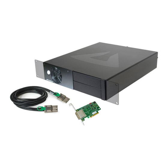
One Stop Systems Pre-Installation Information Before using the OSS PCIe expansion chassis, you should perform the following steps: • Inventory the shipping carton contents for all of the required parts • Gather all of the necessary tools required for installation •... -
Page 12: Components
One Stop Systems Components After completing your inventory, your next step is to be familiarized with components of the OSS EB2200 expansion unit. The expansion unit is composed of the following integral components Expansion Backplane 3 PCIe slots (x8 electrical and x16 mechanical) - Page 13 One Stop Systems ExpressBox 2200 | 1 Introduction...
-
Page 14: Hardware Installation
Tools Required for Installation To complete the installation of the OSS product you will need a Phillips-head screwdriver and ESD wrist strap to prevent electrostatic discharge. The following steps will guide you through the installation of your OSS Expansion System. -
Page 15: Installation-Procedures Overview
One Stop Systems Installation-Procedures Overview Below is the concise version on how to set up the ExpressBox 2200. Open Enclosure Install Expansion Interface card (by default, this is installed) Install Host Interface card into host computer Install PCIe cards (see note below) -
Page 16: Install Expansion Interface Card
Before installing the expansion card, make sure the Dipswitch SW1 is set to ON position (ON=EXP) and Dipswitch SW2 is set to OFF position (x8 setting), see pictures below. The expansion system will NOT function if SW1 is set to OFF=HOST. SW1 and SW2 ExpressBox 2200 | 2 Hardware Installation... -
Page 17: Install Host Interface Card
Check the red Dipswitch (SW1) on the Host interface card, make sure it is set to OFF= HOST. Check the SW2 Dipswitch, both toggle switches are set to OFF position (x8). If the host card is set to expansion mode (ON=EXP), it may not work properly. ExpressBox 2200 | 2 Hardware Installation... -
Page 18: Computer Pcie Slots To Use
Insert the Host interface card into a vacant x8 (or x16) PCIe slot by gently pushing the card until it is firmly seated. Then secure the card into the slot with a mounting screw. To utilize the maximum bandwidth, install the OSS Host interface card into a Gen3 x8 lane slot or Gen2 x8 lane slot. 2.5.1... -
Page 19: Install Pcie Cards
One Stop Systems Install PCIe Cards It is highly recommended to install third party PCI-E cards / High Power PCIe cards after you have verified and tested that the OSS expansion chassis is functional. When installing third Party PCIe card, start with one card first just to see if there are any software and/or hardware issues or incompatibility problems that may occur. -
Page 20: Oss Pcie Slot
2.6.1 OSS PCIe slot The OSS EB2200 expansion chassis has a x8 (electrically), x16 (mechanically) slot. All three slots are compatible with x1, x2, x4, x8 and x16 PCIe cards. It is a x16 connector but it is only electrically wired as a x8 lane. - Page 21 The PCIe slots on the EB2200 expansion chassis are predefined, lanes are not shared amongst PCIe slots, and each slot runs at x8 mode. The OSS Host interface card is also x8. The diagram below represents the speed of PCIe slots that the EB2200 can support.
-
Page 22: Types Of Pcie Cards To Use
One Stop Systems 2.6.2 Types of PCIe cards to use The illustrations below will give you an idea on what PCIe cards you can plug into your EB2200 chassis. ExpressBox 2200 | 2 Hardware Installation... - Page 23 One Stop Systems If you plug in a x16 PCIe card in the OSS EB2200 unit, the card will run at x8 because the OSS PCIe slot is electrically wired as x8 lane. ExpressBox 2200 | 2 Hardware Installation...
-
Page 24: Auxiliary Power Connectors
There are five 4-pin Molex AUX power connectors that can be used for providing extra power to cards. Two (6+2 pin) PCIe connectors for GPUs. Six SATA power connectors One 8-pin CPU / PCIe connector One 6-inch 5.25 Male to Female power adapter ExpressBox 2200 | 2 Hardware Installation... -
Page 25: High Power Pcie Card Installation
75 Watt provided by PCIe slot + One-6pin: 75 Watt + One-6pin: 75 Watt = 225 Watt Number of Pins Watt 6 pin connector provides 75 Watts 8 pin connector provides 150 Watts ExpressBox 2200 | 2 Hardware Installation... -
Page 26: How To Use Oss Auxiliary Power Cable
2.6.5 How to Use OSS Auxiliary Power cable The illustration below will show you how to connect the PCIe / GPU supplied auxiliary power adapter cable to the OSS auxiliary power cable / supply. In this example we are using a singlewide GPU that has six-pin power connector, which draws 150 WATTS of power. - Page 27 One Stop Systems The next example, using a double-wide GPU that has two eight-pin power connectors, which draws 375 Watts of power. ExpressBox 2200 | 2 Hardware Installation...
-
Page 28: Connect Ipass Cable
Connect the iPass cable to Expansion port on the back of the expansion unit. Try not to push the cable with brute force as this can damage the internal connector of the interface card. Connect the other end of the cable to Host computer via Host Interface card. ExpressBox 2200 | 2 Hardware Installation... -
Page 29: How To Disconnect Ipass Cable
After connecting the power cord, turn power supply switch to ON position. NOTE If possible, plug the power cord from the expansion chassis and your host computer into a shared power strip, preferably one that has surge and noise suppression circuitry built into it. ExpressBox 2200 | 2 Hardware Installation... -
Page 30: Connect To Electrical Outlets
You do not need to press the front On/Off switch to turn the expansion unit ON. The unit is remote power on. It will turn ON upon powering UP the host computer. Proceed to next step “Power ON the computer”. ExpressBox 2200 | 2 Hardware Installation... -
Page 31: 2.11 Power On The Computer
ON. ExpressBox 2200 will automatically turn OFF when the computer is turned OFF. The White light on the front of ExpressBox 2200 is not an On-Off power-push button; it is an light indicator that simply indicates whether the chassis is ON or OFF. - Page 32 Host card LED indicator should display five solid green LEDs. It signifies that is training to x8. If you are seeing four solid green LEDs (illuminated) and one amber solid, this is OK. It means that it is training to x4, it is not utilizing its full x8 bandwidth. ExpressBox 2200 |...
-
Page 33: Software Installation
Software Check - Verify Installation You need to check the OSS device and the PCIe card to see if they are all being detected or recognized properly. The following information will guide you on how to check the OSS and PCIe cards on various operating systems. -
Page 34: Check Oss Device - Mac Os X
Check OSS device - Mac OS X In Mac OS X, the OSS expansion device is transparent to the operating system; it means that there will be no OSS hardware / device appearing in the Apple System profiler via PCI card. Only the PCIe cards will be recognized or detected. -
Page 35: Check Oss Device - Linux
Typical output from lspci –vvv is verbose, but you can dig through the information to find very important information. There are many registers and settings associated with PCI Express Switches. Use the “lspci | grep “IDT” command to check that the OSS card slot devices are detected (see image below). IDT is the PCIe switch (component) on the OSS expansion board. - Page 36 One Stop Systems To view the detailed OSS device information for each PCI Bridge, you would need the slot number in the domain:bus:slot.func format, you can query for a particular device as shown below. Based on the lspci –vvv output above we will use 01:00.0 and 02:00.0 . Open the terminal windows and type lspci -s 01:00.0 –vvv and lspci -s 02:00.0 –vvv.
-
Page 37: How To Check Pcie Cards - Mac Os X
If your PCIe cards are still not detected, try another known good card. If this works, it means the problem is with the card. If swapping the PCIe card still exhibiting the same issue, you may have a OSS expansion related problem or the computer is a having issue (i.e. Motherboard). -
Page 38: How To Check Pcie Cards - Windows 7, 8 And 10
If your PCIe cards are still not detected, try another known good card. If this works, it means the problem is with the card. If swapping the PCIe card still exhibiting the same issue, you may have a OSS expansion related problem or the computer is a having issue (i.e. -
Page 39: How To Check Pcie Cards - Linux
To check whether your PCIe cards are detected or recognized on Linux, open the terminal window and type lspci –vtt command. See output below. In this example, there are three GPU cards installed in the OSS EB2200 expansion unit and all of them are recognized. -
Page 40: Additional Technical Information
Connector of the interface card that plugs into a PCIe slot. This can only be installed to a x8 or 16x mechanical PCIe slot. Serial Number Identification number for the card. Each card has their own serial number. ExpressBox 2200 | 4 Additional Technical Information... - Page 41 What is Retimer It cleans up PCI Express signals and is especially useful in signal challenged areas such as transitions between board and backplane. A retimer can improve reliability, run length and performance. ExpressBox 2200 | 4 Additional Technical Information...
-
Page 42: Leds & Dipswitches
4.2.1 Dipswitch SW2 Allows you to set the link width of the card. You can set it to x8 or x4. ExpressBox 2200 | 4 Additional Technical Information... -
Page 43: Dip Switch Sw1
LED indicators The OSS EB2200 is x8. The normal LED on the host interface card should display a x8 link. With a normal and functional host interface card, you should see five solid green LEDs. When the loss of lock LEDs is illuminated, this signifies that the host is training to x4 or it is not utilizing its full x8 bandwidth. -
Page 44: Onboard Visual Diagnostic Features
Multiple LEDs and Dipswitches make debugging and troubleshooting easy. Visible LEDs show the PCIe link width that each PCIe Interface card is operating. Other LEDs for "Loss of Clock", "Reset ON", and "Clock Good" are useful visual indicators for troubleshooting and verifying the connections without expensive software diagnostic tools. ExpressBox 2200 | 4 Additional Technical Information... -
Page 45: Interface Card Dimension
One Stop Systems Interface Card Dimension ExpressBox 2200 | 4 Additional Technical Information... -
Page 46: Backplane / Expansion Board
24 A of +5 V power, the auxiliary connector is required to carry the additional load. These higher levels of power are needed in systems using 250- or 300-watt or greater supplies. ATX Main connector Power Supply main connector ExpressBox 2200 | 4 Additional Technical Information... -
Page 47: Power Leds & Link Up Led
Standby power status LEDs are illuminated when the unit is on standby mode, this means that the expansion unit is awaiting to power up. If you expansion unit fails to power after turning ON the host computer you may have a problem with your OSS cable, expansion card or the host card. -
Page 48: Fan Control Switch
As safety measure, OSS provides an expansion unit with the fan functioning at full speed (MAX). The expansion unit is using a 72 cfm with 5600-RPM fan. However, noise is a concern for many applications. For noise sensitive applications, we have provided this Thermistor setting (THERM) to help alleviate fan noise in situations. -
Page 49: Ipass X8 Cable
Packaging Type Pitch - Mating Interface 0.80mm Single Ended Waterproof / Dustproof Wire Insulation Diameter Wire Size AWG Wire/Cable Type Round Electrical Current - Maximum per Contact 1.0A Shielded Voltage - Maximum 30V DC ExpressBox 2200 | 4 Additional Technical Information... -
Page 50: Internal Front Fan Specifications
When purchasing a replacement fan we recommend buying a certified OSS fan. The part number for the fan with wire leads terminated and with proper connectors is 01-05941-00. The fan itself (w/o the wire leads terminated) is 26-00038-00. Use part# 01-05941-00 when purchasing the replacement fan. -
Page 51: 4.10 Power Supply - Fanless
Gold Plated High Current Terminals Dual Sided PCB Layout Ultra Ventilation [Honeycomb Structure] Multi-GPU Technology Support All-in-One DC Cabling Design Easy Swap Connector Universal AC Input 4.10.2 PSU Specifications ExpressBox 2200 | 4 Additional Technical Information... -
Page 52: Power Distribution
One Stop Systems 4.10.3 Power Distribution 4.10.4 Wire Configuration ExpressBox 2200 | 4 Additional Technical Information... -
Page 53: How To Remove & Install Parts
Disconnect the Fan power cable assembly from the board using a long-nosed pliers. Remove the four mounting screws from the front panel. Pull the front panel out from the chassis. ExpressBox 2200 | 5 How to Remove & Install Parts... -
Page 54: How To Remove The Power Supply
Remove the four screws from the back of the unit. Pull the power supply out from the chassis. Disconnect the main ATX power connector. Unplug the two PCIe power connectors. ExpressBox 2200 | 5 How to Remove & Install Parts... -
Page 55: How To Remove The Expansion Board
Remove all screws on the expansion board. Slowly lift the expansion board and unplug the Fan power cable assembly. Disconnect the ATX power cable from the board. Unplug the PCIe power cable. ExpressBox 2200 | 5 How to Remove & Install Parts... - Page 56 One Stop Systems Disconnect the ON/OFF switch power cable assembly. Remove Expansion Interface card. Remove all screws on the expansion board. Slowly lift the expansion board. Unplug the Fan power cable assembly. ExpressBox 2200 | 5 How to Remove & Install Parts...
-
Page 57: Rack Mount Kit Installation
Remove two screws front the right side, remove small panel. Prepare rack mount ears (kit). Mount and secure the front left rack mount ear. Mount and secure front right rack mount ear. ExpressBox 2200 | 5 How to Remove & Install Parts... - Page 58 One Stop Systems Remove four screws, and then pull the front panel out from the enclosure. Remove two screws on front the right side, remove small panel. Prepare rack mount ears (kit). ExpressBox 2200 | 5 How to Remove & Install Parts...
- Page 59 One Stop Systems Mount and secure the front left rack mount ear. Mount and secure front right rack mount ear. ExpressBox 2200 | 5 How to Remove & Install Parts...
-
Page 60: Rackmount Rear Ears Installation
Attached and secure the right side rear ear bracket. Insert the sliding rear ear. Mount the left side rear ears. Attach and secure the rear bracket to the back of the expansion unit. ExpressBox 2200 | 5 How to Remove & Install Parts... - Page 61 One Stop Systems Insert the sliding rear ear. Mount the right side rear ears. Attached and secure the right side rear ear bracket. ExpressBox 2200 | 5 How to Remove & Install Parts...
- Page 62 One Stop Systems Insert the sliding rear ear ExpressBox 2200 |...
-
Page 63: Troubleshooting
If it boots up OK without the OSS expansion system attached,, you may have a problem with your OSS host card or expansion chassis. You need to send this expansion unit for service. If it still hangs, the problem is in the computer and not with the OSS expansion system or the third Party PCI cards. Try another computer. ... -
Page 64: My Pcie Card Doesn't Work
Party PCI Cards OSS will provide reasonable technical support to with third Party PCI cards. However, if you have verified a successful installation of the OSS PCI Expansion System but having difficulty installing your third Party PCIe cards, the PCI card manufacturer may be able to provide the best support. -
Page 65: Frequently Asked Questions (Faq)
A. Turn off the computer. Disconnect the OSS iPass cable. Remove power cord from OSS. Remove and reseat PCIe card. Reconnect the iPass cable to computer and plug-in power cord to OSS. Turn on the ON the expansion unit. This should automatically turn on the OSS expansion unit. - Page 66 Q; My PCIe host card is only showing one orange / amber LED after powering up the host computer; do I have a bad Host card? A: The OSS interface card is not coming out of reset. This means the OSS interface card is not compatible with the computer motherboard. Try another model or different brand of computer.
-
Page 67: How To Get More Help
OSS for warranty repair/ replacement or take advantage of the 30-day money back guarantee, you will need to package the product in a manner similar to the manner in which it was received from our plant. OSS cannot be responsible for any physical damage to the product or component pieces of the product that are damaged due to inadequate packing. -
Page 68: Items & Part Numbers
When placing an order for spare parts or items, use the following part numbers. To order parts, please to contact OSS Sales, 760-745-9883 or send an email to sales@OSS.com. You can also submit an online sales request using the online contact form, http://OSS.com/contact-us/... -
Page 69: Appendix A Multiple Expansion System Configurations
PCIe slots beyond the number available in your computer’s motherboard. You can easily add two or more OSS expansion systems to your current system in either a "fan-out" or "daisy-chain" configuration. Each of these configurations has advantages and uses. -
Page 70: Fan-Out
Install the Interface card in the computer, use available PCIe slot, preferably use x16 @ x8 lane. Connect OSS cables. Connect power cords. Turn power supply with to “ON” position Power UP the computer All expansion units should power up automatically. ExpressBox 2200 | 8 Appendix A Multiple Expansion System Configurations... -
Page 71: Daisy-Chaining
Set the Interface card to “Host” mode. Check the SW4 switch. Move the switch to “OFF-Host” position. Install the Interface card in the Expansion unit, use available PCIe slot. Connect OSS cables. Connect power cords. Turn power supply with to “ON” position Power UP the computer All expansion units should power up automatically. ExpressBox 2200 |... -
Page 72: Appendix Bpci Express General Information
The x16 is the largest size in common use. The lane count of a PCIe card or the PCIe slot is a determining factor its performance. ExpressBox 2200 | 9 Appendix B PCI Express General Information... -
Page 73: Pci Express Links And Lanes
When computer starts up, the BIOS detects and enumerates all devices that are plugged into the CPU-motherboard. It then identifies the links between the devices and creating a map of where the traffic will go and negotiating the width of each link. ExpressBox 2200 | 9 Appendix B PCI Express General Information... -
Page 74: Form Factor
“xsize” @ xspeed” notation (“x16 @ x4”) is also common. The advantage is that such slots can accommodate a larger range of PCI Express cards without requiring motherboard hardware to support the full transfer rate. ExpressBox 2200 | 9 Appendix B PCI Express General Information... -
Page 75: Bandwidth
“x2” connection. Although in theory any number from one to 32 lanes can be grouped, the most common numbers are x4, x8, and x16. ExpressBox 2200 | 9 Appendix B PCI Express General Information... - Page 76 32 extra bits are needed (two for every eight bits). Because of this lower overhead requirement, PCI Express 3.0 can achieve double the PCI Express 2.0 bandwidth with a clock rate of 8 GHz instead of 10 GHz. ExpressBox 2200 | 9 Appendix B PCI Express General Information...
-
Page 77: Power
Auxiliary Power Connector Configuration 75 Watts None 150 Watts One six-pin connector 225 Watts Two six-pin connectors* 300 Watts One eight-pin connector + one six-pin connector 375 Watts Two eight-pin connectors 450 Watts Two eight-pin connectors + one six-pin connector ExpressBox 2200 |... -
Page 78: Appendix C Compliance
Cetappareilnumériqué de la classe A estconformé à la norme NMB-003 du Canada 10.2 CE The product(s) described in this manual complies with all applicable European Union (CE) directives. OSS will not retest or recertify systems or components that have been reconfigured by customers... - Page 79 Manual P/N 09-09959-02 Rev A...
Need help?
Do you have a question about the ExpressBox 2200 and is the answer not in the manual?
Questions and answers