Table of Contents
Advertisement
Quick Links
PZ268D
P-616 NanoCube® XYZ Nanopositioner
User manual
Version: 1.1.0
Physik Instrumente (PI) GmbH & Co. KG, Auf der Roemerstrasse 1, 76228 Karlsruhe, Germany
Phone +49 721 4846-0, Fax +49 721 4846-1019, Email info@pi.ws, www.pi.ws
Date: 14.01.2022
This document describes the following product:
P-616.3C
Parallel-kinematic NanoCube® XYZ
nanopositioner, 100 µm × 100 µm × 100 µm
travel range, capacitive sensors
Advertisement
Table of Contents

Related Manuals for PI P-616 NanoCube


Summary of Contents for PI P-616 NanoCube
- Page 1 Parallel-kinematic NanoCube® XYZ nanopositioner, 100 µm × 100 µm × 100 µm travel range, capacitive sensors Physik Instrumente (PI) GmbH & Co. KG, Auf der Roemerstrasse 1, 76228 Karlsruhe, Germany Phone +49 721 4846-0, Fax +49 721 4846-1019, Email info@pi.ws, www.pi.ws...
- Page 2 The patents held by PI are found in our patent list: https://www.physikinstrumente.com/en/about-pi/patents © 2022 Physik Instrumente (PI) GmbH & Co. KG, Karlsruhe, Germany. The text, photographs and drawings in this manual are protected by copyright. With regard thereto, Physik Instrumente (PI) GmbH & Co. KG retains all the rights.
-
Page 3: Table Of Contents
Contents About this Document Objective and Target Audience of this User Manual..........1 Symbols and Typographic Conventions..............1 Figures ........................2 Other Applicable Documents ..................2 Downloading Manuals ....................2 Safety Intended Use ......................5 General Safety Instructions ..................5 Organizational Measures .................... - Page 4 Maintenance General Notes on Maintenance ................33 Cleaning the P-616 ....................33 Troubleshooting Customer Service Technical Data 10.1 Specifications ......................39 10.1.1 Data Table ....................39 10.1.2 Maximum Ratings ..................40 10.1.3 Ambient Conditions and Classifications ............41 10.2 Dimensions ....................... 42 10.3 Torque for Stainless Steel Screws (A2-70) ..............
-
Page 5: About This Document
Precautionary measures for avoiding the risk. NOTICE Dangerous situation Failure to comply could cause damage to equipment. Precautionary measures for avoiding the risk. INFORMATION Information for easier handling, tricks, tips, etc. P-616 NanoCube® XYZ Nanopositioner PZ268D Version: 1.1.0... -
Page 6: Figures
Other Applicable Documents The devices and software tools from PI mentioned in this documentation are described in separate manuals. The latest versions of the user manuals are available for download (p. 2) on our website. - Page 7 1 About this Document Downloading Manuals 1. Open the website www.pi.ws. 2. Search the website for the product number (e.g., P-882) or the product family (e.g., PICMA® bender). 3. Click the corresponding product to open the product detail page. 4. Click the Downloads tab.
-
Page 9: Safety
The intended use of the P-616 is only possible in conjunction with suitable electronics (p. 11) available from PI. The electronics are not included in the scope of delivery of the P-616. The electronics must provide the required operating voltages. For closed-loop operation, it must be in a position to read out and process the signals of the position sensors. -
Page 10: Organizational Measures
Do the work only if the user manual is complete. Missing information due to an incomplete user manual can result in minor injury and damage to equipment. Install and operate the P-616 only after you have read and understood this user manual. Version: 1.1.0 PZ268D P-616 NanoCube® XYZ Nanopositioner... - Page 11 2 Safety Personnel qualification The P-616 may only be installed, started, operated, maintained, and cleaned by authorized and appropriately qualified personnel. P-616 NanoCube® XYZ Nanopositioner PZ268D Version: 1.1.0...
-
Page 13: Product Description
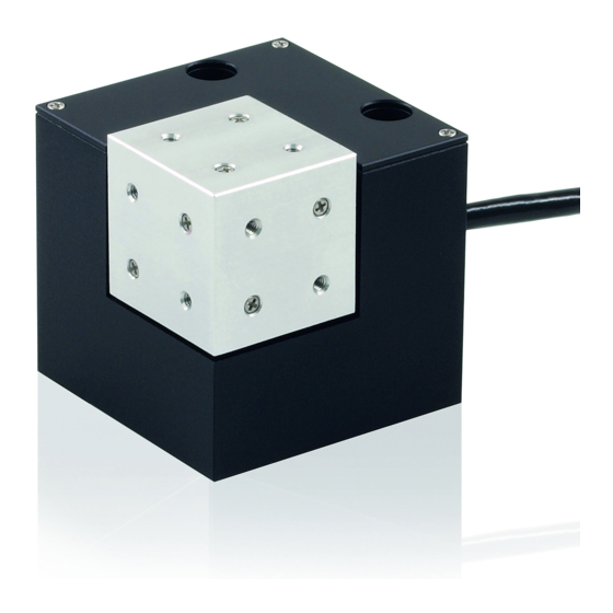
Countersunk bore (2×) for mounting onto surface Cable exit (supply voltage, sensor) M4 hole for protective earth connector The arrows indicate the positive direction of motion in each case. The letters X, Y, and Z indicate the axis. P-616 NanoCube® XYZ Nanopositioner PZ268D Version: 1.1.0... -
Page 14: Product Labeling
× 100 µm travel range, capacitive sensors 000036450 M4 screw set for protective earth, consisting of: One flat-head screw with cross recess, M4x8, ISO 7045 2 lock washers 2 flat washers Version: 1.1.0 PZ268D P-616 NanoCube® XYZ Nanopositioner... -
Page 15: Optional Accessories
Fiber holder 90° for P-616, with fiber optic ferrules 1.25 mm, 2.5 mm, and 3.2 mm To order, contact our customer service department (p. 37). Suitable Electronics The P-616 must be connected to suitable electronics. The following devices from PI are suitable for operation of the P-616: Product number Description E-727.3CD... -
Page 16: Technical Features
The P-895.3DLC adapter cable is necessary for the analog controller and/or E-500/E-501 and E- 663 drivers, available as optional accessories (p. 11). PC software is included in the scope of delivery of the controllers from PI. The operation of the controllers is described in the corresponding user manuals. -
Page 17: Unpacking
3. Inspect the contents for signs of damage. If any parts are damaged or missing, contact our customer service department (p. 37) immediately. 4. Keep all packaging materials in case the product needs to be returned. P-616 NanoCube® XYZ Nanopositioner PZ268D Version: 1.1.0... -
Page 19: Installation
Do not open the P-616. Discharge the positioner's piezo actuators before installing: Connect the positioner to the switched-off PI electronics equipped with an internal discharge resistor. Do not pull the plug connector out of the electronics during operation. -
Page 20: Connecting The P-616 To The Protective Earth Conductor
NOTICE Damage due to unsuitable cables! Unsuitable cables can damage the P-616 and the electronics. Use cables provided by PI only to connect the P-616 to the electronics. NOTICE Damage due to improper mounting! Improper mounting of the P-616 or incorrectly mounted parts can damage the P-616. - Page 21 3. Tighten the M4 screw with a torque of 1.2 Nm to 1.5 Nm. 4. Make sure that the contact resistance at all connection points relevant for connecting the protective earth conductor is <0.1 Ω at 25 A. P-616 NanoCube® XYZ Nanopositioner PZ268D Version: 1.1.0...
-
Page 22: Mounting The P-616
Pull forces on the connecting cable and bending the cable can damage the P-616. Avoid pull forces on the connecting cable. Install the P-616 so that the cable is not bent or crushed too strongly. Version: 1.1.0 PZ268D P-616 NanoCube® XYZ Nanopositioner... - Page 23 1. Align the P-616 on an even surface. Optional: Use the locating pins to align the P-616 on the surface. 2. Insert the screws from above into the countersunk holes in the base body of the P-616. 3. Tighten the screws. Maximum torque: 1.1 Nm P-616 NanoCube® XYZ Nanopositioner PZ268D Version: 1.1.0...
-
Page 24: Fixing The Load
If the center of the load to be fixed is too high or to the side of the motion platform, adjust the controller settings before startup or contact our customer service department (p. 37). Respect the leverage effect of the fiber holder. Ensure sufficient strain relief of the connected fibers. Version: 1.1.0 PZ268D P-616 NanoCube® XYZ Nanopositioner... - Page 25 Pay attention to the depth of the mounting holes in the platform (p. 42). Use screws of the correct length for the respective mounting holes only. INFORMATION Positive direction of axis motion is specified in the product view (p. 9). P-616 NanoCube® XYZ Nanopositioner PZ268D Version: 1.1.0...
- Page 26 Center of load at the optimum position: Figure 7: Example of an optimally placed load Load center Center of load at an unsuitable position: Figure 8: Tall load and center of load too far above the motion platform Version: 1.1.0 PZ268D P-616 NanoCube® XYZ Nanopositioner...
- Page 27 The P-616 is not connected to the electronics. Tools and accessories M2 screws of suitable length, see "Dimensions" (p. 42) Suitable tools Fixing the load Fix loads only by inserting suitable screws into the threaded holes provided: P-616 NanoCube® XYZ Nanopositioner PZ268D Version: 1.1.0...
-
Page 28: Fixing The Fiber Holder
Fix the load so that its center is in the middle of the XYZ mounting platform. Fixing the fiber holder XYZ mounting platform Figure 11: The arrows show the screws used to disassemble the XYZ mounting platform. Version: 1.1.0 PZ268D P-616 NanoCube® XYZ Nanopositioner... - Page 29 1. Disassemble the XYZ platform from the P-616 using the screws shown in the figure at the top left. 2. Using suitable screws, fix the fiber holder to the six threaded holes, see the figure on the top right. Maximum torque: 0.3 Nm P-616 NanoCube® XYZ Nanopositioner PZ268D Version: 1.1.0...
-
Page 30: Connecting The P-616 To The Electronics
P1 to P for channel 1 (SERVO 1) − − T2 to T for channel 2 (SERVO 2) P2 to P for channel 2 (SERVO 2) − − T3 to T for channel 3 (SERVO 3) Version: 1.1.0 PZ268D P-616 NanoCube® XYZ Nanopositioner... - Page 31 5 Installation − P3 to P for channel 3 (SERVO 3) P-616 NanoCube® XYZ Nanopositioner PZ268D Version: 1.1.0...
-
Page 33: Starting And Operating
Applying a continuous high static voltage to piezo actuators leads to a considerable reduction in the lifetime of the piezo ceramic. When the P-616 is not used but the electronics remain switched on to ensure temperature stability, discharge the P-616 (p. 30). P-616 NanoCube® XYZ Nanopositioner PZ268D Version: 1.1.0... -
Page 34: Operating The P-616
Operating voltages that are too high or incorrectly connected can cause damage to the P-616. Operate the P-616 only with controllers/drivers and original accessories from PI. Do not exceed the operating voltage range (p. 40) for which the P-616 is specified. - Page 35 Before demounting (e.g., before cleaning and transporting the P-616 and for modifications) The P-616 is discharged via the discharge resistor inside the electronics from PI. Discharging a positioner connected to the electronics In closed-loop operation: 1. Switch off the servo mode on the controller.
-
Page 37: Maintenance
You have disconnected the P-616 from the electronics. Cleaning the P-616 Clean the surfaces of the P-616 with a cloth dampened with a mild cleanser or disinfectant (e.g., isopropyl alcohol). Do not do any ultrasonic cleaning. P-616 NanoCube® XYZ Nanopositioner PZ268D Version: 1.1.0... -
Page 39: Troubleshooting
The assignment is indicated controller (only when on the calibration label of the controller there are several (see rear panel or bottom), which systems) contains the serial number of the positioner to be connected. P-616 NanoCube® XYZ Nanopositioner PZ268D Version: 1.1.0... - Page 40 If the problem that occurred with your system is not listed in the table above or cannot be solved as described, contact our customer service department ( (p. 37)). Version: 1.1.0 PZ268D P-616 NanoCube® XYZ Nanopositioner...
-
Page 41: Customer Service
9 Customer Service Customer Service For inquiries and orders, contact your PI sales engineer or send us an email (service@pi.de). If you have any questions concerning your system, provide the following information: Product and serial numbers of all products in the system −... -
Page 43: Technical Data
Resonant frequency X / Y / Z, ±10 % unloaded Resonant frequency with 30 g load X / ±20 % Y / Z Resonant frequency with 100 g load X ±20 % / Y / Z P-616 NanoCube® XYZ Nanopositioner PZ268D Version: 1.1.0... -
Page 44: Maximum Ratings
D-sub 25W3 (m) Recommended electronics E-503, E-663, E-712, E-727 The resolution of the system is limited only by the noise of the amplifier and the measuring technology because PI piezo nanopositioning systems are free of friction. 10.1.2 Maximum Ratings P-616 positioners are designed for the following operating data:... -
Page 45: Ambient Conditions And Classifications
-20 °C to 80 °C Storage temperature -20 °C to 80 °C Transport temperature -25 °C to 85 °C Overvoltage category Protection class Degree of pollution Degree of protection IP20 according to IEC 60529 P-616 NanoCube® XYZ Nanopositioner PZ268D Version: 1.1.0... -
Page 46: Dimensions
10 Technical Data 10.2 Dimensions Dimensions in mm. Note that the decimal points are separated by a comma in the drawings. Figure 14: P-616.3C Cable exit Version: 1.1.0 PZ268D P-616 NanoCube® XYZ Nanopositioner... -
Page 47: Torque For Stainless Steel Screws (A2-70)
Target sensor signal, channel 2 Input (moving part of the capacitive sensor) Target sensor signal, channel 3 Input (moving part of the capacitive sensor) ID chip ground, channel 1 Bidirectional Data line for ID-Chip, channel 1 P-616 NanoCube® XYZ Nanopositioner PZ268D Version: 1.1.0... - Page 48 Piezo voltage –, channel 3 Input Piezo voltage –, channel 2 Input Piezo voltage –, channel 1 Shielding for target sensor signal, channel 1 * The "-" sign indicates that the corresponding pin has not been assigned. Version: 1.1.0 PZ268D P-616 NanoCube® XYZ Nanopositioner...
-
Page 49: Old Equipment Disposal
Dispose of your old equipment according to international, national, and local rules and regulations. In order to fulfil its responsibility as the product manufacturer, Physik Instrumente (PI) GmbH & Co. KG undertakes environmentally correct disposal of all old PI equipment made available on the market after 13 August 2005 without charge. - Page 51 For the P-616, declarations of conformity were issued according to the following European statutory requirements: Low Voltage Directive EMC Directive RoHS Directive The standards applied for certifying conformity are listed below. Safety (Low Voltage Directive): EN 61010-1 EMC: EN 61326-1 RoHS: EN IEC 63000 P-616 NanoCube® XYZ Nanopositioner PZ268D Version: 1.1.0...
Need help?
Do you have a question about the P-616 NanoCube and is the answer not in the manual?
Questions and answers