Table of Contents
Advertisement
Quick Links
User Manual
A141D001 Rev 1.2
26-March-2020
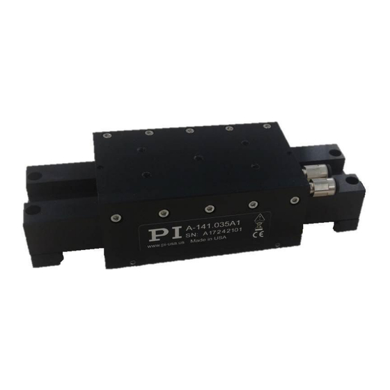
A-141 Series Miniature Linear Air Bearing Stage
This document describes the A-141.xxxxx Series of Linear Air Bearing Motorized Stages.
PI (Physik Instrumente) L.P.
16 Albert Street, Auburn, MA 01501
Tel: 508-832-3456 Fax: 508-832-0506
Email: air@pi-usa.us
Page 1 of 25
Advertisement
Table of Contents

Related Manuals for PI A-141 Series


Summary of Contents for PI A-141 Series
- Page 1 User Manual A141D001 Rev 1.2 26-March-2020 A-141 Series Miniature Linear Air Bearing Stage This document describes the A-141.xxxxx Series of Linear Air Bearing Motorized Stages. Page 1 of 25 PI (Physik Instrumente) L.P. 16 Albert Street, Auburn, MA 01501 Tel: 508-832-3456 Fax: 508-832-0506...
- Page 2 PI owns the following patents or patent applications for the technology field Magnetic Direct Drives (PIMag®): WO212146709A2, DE102012207082A1 © 2020 PI (Physik Instrumente) L.P. The text, photographs and drawings in this manual are protected by copyright. With regard thereto, PI (Physik Instrumente) L.P. retains all the rights. Use of said text, photographs and drawings is permitted only in part and only upon citation of the source.
-
Page 3: Table Of Contents
Air Supply _________________________________________________________________________ 15 6.5. Affixing the Payload to the Stage ______________________________________________________ 16 6.6. XY and Vertical Configurations ________________________________________________________ 17 Page 3 of 25 PI (Physik Instrumente) L.P. 16 Albert Street, Auburn, MA 01501 Tel: 508-832-3456 Fax: 508-832-0506 Email: air@pi-usa.us... - Page 4 Figure 4 - Shipping Restraint________________________________________________________________ 14 Figure 5 - Air Inlet Fittings __________________________________________________________________ 15 Figure 6 - Payload Mounting Holes ___________________________________________________________ 16 Figure 7 - A-141 Series Stage Dimensions _____________________________________________________ 23 Page 4 of 25 PI (Physik Instrumente) L.P. 16 Albert Street, Auburn, MA 01501 Tel: 508-832-3456 Fax: 508-832-0506 Email: air@pi-usa.us...
-
Page 5: About This Document
Objective and Target Audience of this User Manual This manual contains information on the intended use of the A-141 series of linear motor-driven air bearing stages. It assumes that the reader has a fundamental understanding of basic servo systems as well as motion control concepts and applicable safety procedures. -
Page 6: Safety
Immediately eliminate any faults and malfunctions that are likely to affect safety. The operator is responsible for the correct installation and operation of the A-141. Page 6 of 25 PI (Physik Instrumente) L.P. 16 Albert Street, Auburn, MA 01501 Tel: 508-832-3456 Fax: 508-832-0506 Email: air@pi-usa.us... -
Page 7: Warnings And Safety Notices
Dirt, oil, lubricants and condensation will damage the stage. Keep the stage clean and free of dirt, debris, oil, lubricants, and moisture. Page 7 of 25 PI (Physik Instrumente) L.P. 16 Albert Street, Auburn, MA 01501 Tel: 508-832-3456 Fax: 508-832-0506... -
Page 8: Organizational Measures
Personnel qualification The A-141 may only be installed, started up, operated, maintained and cleaned by authorized and appropriately qualified personnel. Page 8 of 25 PI (Physik Instrumente) L.P. 16 Albert Street, Auburn, MA 01501 Tel: 508-832-3456 Fax: 508-832-0506 Email: air@pi-usa.us... -
Page 9: Product Description
3.2. Product Features The A-141 series stage incorporates completely non-contact air bearing surfaces, linear motors, and feedback devices to provide a maintenance free stage. There is no mechanical contact to wear or require lubrication, making these stages ideal for clean room and medical applications. The A-141 incorporates opposing lateral and vertical preload. -
Page 10: Product Labeling
Stage Mounting Screws (M6 x 40 SHCS) Shipping restraint A141D001 User manual (this document) 3.5. Accessories The following accessories are offered to complement the A-141 stage. Contact PI for all available configurations. Part # Description A-80x.xxx Air Preparation and Filtration Kit A-851.xxx... -
Page 11: Controllers
Limits and Index Mark The A-141 series stage features non-contact limit switches and a home index marker. Both the limits and the index position are integral to the encoder electronics. The limits are magnetic and active high and are placed near the ends of travel. -
Page 12: Unpacking And Handling
Carefully unpack the air bearing stage and other components from the shipping packaging. Inspect the contents for signs of damage. If there is any sign of damage or missing parts, contact PI immediately. Compare the package contents to packing list and notify PI immediately if any parts are missing or incorrect. Keep all packaging materials in case the product needs to be returned. -
Page 13: Installation
The mounting surface should be flat and have adequate stiffness in order to achieve the maximum performance from the A-141. When the A-141 series stage is mounted to a non-flat surface, the stage can be distorted as the mounting screws are tightened. This distortion will decrease the overall accuracy of the stage. Adjustments to the mounting surface must be done before the stage is secured. -
Page 14: Removing The Shipping Restraint
The shipping restraint kit for the A-141 consists of: Description Shipping bracket for A-141 (1x) M2.5 Pan Head screws, 8mm Long (2x) Page 14 of 25 PI (Physik Instrumente) L.P. 16 Albert Street, Auburn, MA 01501 Tel: 508-832-3456 Fax: 508-832-0506 Email: air@pi-usa.us... -
Page 15: Air Supply
By turning the main top/lift supply on or off while keeping the side/bottom supply on, the stage position can be locked. This can be done while a servo loop in enabled. Contact PI for more information about using this feature. -
Page 16: Affixing The Payload To The Stage
Do not exceed the maximum payload specified for the A-141 stage. Payload CG should not be cantilevered beyond the extents of the stage table. Page 16 of 25 PI (Physik Instrumente) L.P. 16 Albert Street, Auburn, MA 01501 Tel: 508-832-3456 Fax: 508-832-0506... -
Page 17: Xy And Vertical Configurations
Connecting the Cables Stage interconnect cables are not in the scope of delivery of the A-141 series stage. However, PI offers several standard cable sets that can be used, depending on the motion controller being used. Contact PI for a quote. -
Page 18: Startup And Operation Of The Stage
Note that the servo tuning values may need to be adjusted if the payload mass or size changes. If PI was not given user application information at the time of order, the servo was tuned with no (zero) payload mass. -
Page 19: Maintenance
User Manual A141D001 Rev 1.2 26-March-2020 Maintenance Other than basic cleaning, the A-141 series stage is maintenance-free. 8.1. Cleaning the Stage To clean the stage bearing surfaces, use isopropanol and a clean, lint-free cloth or wipe. Apply the cleaning agent to the cloth and wipe down all of the air bearing surfaces. When cleaning the air bearing it is recommended to leave the air supply turned on to help blow any particles out of the bearing and prevent particles from entering the nozzles. -
Page 20: Customer Service
User Manual A141D001 Rev 1.2 26-March-2020 Customer Service For inquiries and orders, contact your PI sales engineer or use the following contacts: Email: air@pi-usa.us Address: 16 Albert Street, Auburn, MA 01501, USA Tel: 508-832-3456 Fax: 508-832-0506 If you have questions concerning your system, have the following information ready: ... -
Page 21: Technical Data
Assumes an air bearing operating pressure of 70 psi (480 kPa. Stage is designed for horizontal operation only. Accuracy is obtained with controller-based error compensation. The stage must be ordered with a controller from PI to reach these values. Accuracy values assume short-term duration and do not consider the long-term effects of thermal drift on the stage. -
Page 22: Motor Electrical Specifications
Operating temperature +15°C to +25°C Storage temperature 0°C to +40°C in original packaging Dust Exposure The A-141 series stage is not suited for dusty, dirty, oily, or wet environments. Overvoltage Category Protection Class Degree of Pollution Degree of protection according to... -
Page 23: Dimensions
User Manual A141D001 Rev 1.2 26-March-2020 10.5. Dimensions Figure 7 - A-141 Series Stage Dimensions Page 23 of 25 PI (Physik Instrumente) L.P. 16 Albert Street, Auburn, MA 01501 Tel: 508-832-3456 Fax: 508-832-0506 Email: air@pi-usa.us... -
Page 24: Pin Assignments
Encoder Analog Sine + Index - Encoder Analog Reference - Encoder ground GND Sense Encoder ground sense line Encoder Calibration Page 24 of 25 PI (Physik Instrumente) L.P. 16 Albert Street, Auburn, MA 01501 Tel: 508-832-3456 Fax: 508-832-0506 Email: air@pi-usa.us... -
Page 25: Ec Declaration Of Conformity
Dispose of your old equipment according to international, national, and local rules and regulations. In order to fulfil its responsibility as the product manufacturer, Physik Instrumente (PI) GmbH & Co. KG undertakes environmentally correct disposal of all old PI equipment made available on the market after 13 August 2005 without charge.
Need help?
Do you have a question about the A-141 Series and is the answer not in the manual?
Questions and answers