Veeder-Root TLS-4 Series Troubleshooting Manual
Hide thumbs
Also See for TLS-4 Series:
- Manual (699 pages) ,
- Console hardware replacement (16 pages) ,
- Programming and troubleshooting (4 pages)

Related Manuals for Veeder-Root TLS-4 Series


Summary of Contents for Veeder-Root TLS-4 Series
- Page 1 Revision: D Manual No: 577013-918 ● Software Version 3A TLS-4XX Series Consoles Troubleshooting Guide...
- Page 2 Customer Service will work with production facility to have the replacement product shipped as soon as possible. If “lost” equipment is delivered at a later date and is not needed, Veeder-Root will allow a Return to Stock without a restocking fee.
-
Page 3: Table Of Contents
Table of Contents 1 Introduction Related Manuals ......................1-1 Contractor Certification Requirements ................1-1 Safety Precautions ......................1-2 Safety Warnings ......................1-2 2 System Description System Parts Identification ....................2-1 Basic Troubleshooting Procedures ................2-10 Intrinsic Safety Check ....................2-10 Visual Inspection of Console Interior ................2-11 Test Front Panel LEDs, Display, and Console Beeper ..........2-11 3 Software Version Feature List Verifying Installed System Features ................3-1 4 Fuses... - Page 4 Table of Contents 8 Probe Troubleshooting Field Troubleshooting Probe-Out Alarms ...............8-3 Minimum Detected Fluid Levels ..................8-5 Mag Probe Channel Counts in Common Liquids ............8-6 9 Sensor Troubleshooting Sensor Alarm Will Not Clear ..................9-1 Sensor Out Alarms ......................9-1 Setup Data Warning ......................9-1 Unstable Sensor Readings ....................9-1 Cleaning Fuel Contaminated Discriminating Sensors ............9-2 Discriminating Sensors 794380-320, -322, -350, -352 ..........9-2...
- Page 5 Table of Contents Figures Figure 2-1. Console Front Panel................Figure 2-2. Printer door assembly ................. Figure 2-3. Display door assembly ................ Figure 2-4. Console board locations ..............Figure 2-5. AC Input board ..................Figure 2-6. Power Supply board ................Figure 2-7. I/O Backplane board................
-
Page 6: Introduction
TLS Consoles Point-of-Sale (POS) Application Guide Contractor Certification Requirements Veeder-Root requires the following minimum training certifications for contractors who will troubleshoot the equipment discussed in this manual: Installer Certification: Contractors holding valid Installer Certification are approved to perform wiring and conduit routing, equipment mounting, probe and sensor installation, tank and line preparation, and line leak detector installation. -
Page 7: Safety Precautions
National Electrical Codes 70 and 30A; federal, state, and local codes; and other applicable safety codes. 3. Substitution of components may impair intrinsic safety. 4. Do not modify or use service parts other than those provided by Veeder-Root. -
Page 8: System Description
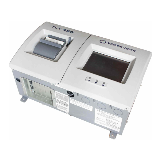
System Description System Parts Identification The following figures identify the components and printed circuit boards of the TLS-4XX Series consoles. consoles\450\918-1.eps LEGEND Item Description Item Description Optional integral printer (Printer Door Touch screen (Display Door Assembly) Assembly) LED Status indicators Green LED - System Normal Yellow LED - Active Warning Red LED - Active Alarm... -
Page 9: Figure 2-2. Printer Door Assembly
System Description System Parts Identification consoles\450\918-3.eps LEGEND Item Description Item Description Paper roll release lever Connector for data input cable to JUSB1 on CPU board Printer assembly Paper cover Connector for power input cable to J1 on Power Supply board Figure 2-2. -
Page 10: Figure 2-3. Display Door Assembly
System Description System Parts Identification consoles\450\918-4.eps Section A-A LEGEND Item Description Item Description Touch screen display assembly Cable to display data connector on CPU board Input Module Connection Labels Cable to AC Inverter board Cable to touch screen connector on CPU board AC Inverter board Figure 2-3. -
Page 11: Figure 2-4. Console Board Locations
System Description System Parts Identification J1 J1 T1 T1 R1 R1 U1 U1 M1 M1 D1 D1 L2 L2 F3 F3 L1 L1 Q1 Q1 +12V +12V T3 T3 T2 T2 F4 F4 FID3 FID3 L3 L3 J4 J4 WARNING: TO MAINTAIN WARNING: TO MAINTAIN WARNING: TO MAINTAIN WARNING: TO MAINTAIN... -
Page 12: Figure 2-5. Ac Input Board
System Description System Parts Identification RELAY A/C INPUT 250 V SLO-BLO RELAY JJL 07/02/07 A/C INPUT BOARD 332662-001 CONTROL +12V A/C TO POWER SUPPLY consoles\450\918-7.eps LEGEND Item Description Item Description AC input power connector Output relay control connects to J3 on Power Supply board) Output relay control connector Console AC Input to J2 on Power Sup-... -
Page 13: Figure 2-6. Power Supply Board
System Description System Parts Identification L2 L2 L2/N +12V FID2 FID3 +12V consoles\450\918-8.eps LEGEND Item Description Item Description Low voltage relay control connector Printer power supply fuse, 3A Slo-Blo (Relay connector on AC input board connects here) AC Input power connector (Line AC Console power supply fuse, 3A Slo- input connector on AC input board connects here) -
Page 14: Figure 2-7. I/O Backplane Board
System Description System Parts Identification TO COMM I/O BACKPLANE TO EXPANSION SPARE SPARE EXT_ EXT_RESET RESET 332616-002 SNAP SCREW SCREW +24V +24V +24V +24V 332616-001 I/O BACKPLANE EXT_RESET +24V SLOT 2 SLOT 3 SLOT 4 SLOT 1 SNAP SNAP SNAP G G B B F F JJL012907 consoles\450\918-7.eps... -
Page 15: Figure 2-8. Comm Backplane Board
System Description System Parts Identification J2 J2 NO COMPONENTS OR TRACES ABOVE THIS LINE BD Group - Comm.Backplane board TLS-450 console 332881-001 Rev A VRBUS_RST VRBUS- SLOT 1 SLOT 2 SLOT 3 SLOT 5 SLOT 4 VRBUS+ +24V +24V 29 29 30 30 29 29 30 30... -
Page 16: Figure 2-9. Cpu Board
System Description System Parts Identification 15 15 Console Port Console Port Z3 Z3 Z5 Z5 FUD2 FUD2 C249 C249 Touch Screen Header Touch Screen Header C117 C117 J8 J8 P1 P1 C275 C275 FUD3 FUD3 16 16 Grayscale LCD Interface Grayscale LCD Interface Main Memory Main Memory... -
Page 17: Basic Troubleshooting Procedures
System Description Basic Troubleshooting Procedures Basic Troubleshooting Procedures To ensure proper and safe troubleshooting and repair procedures for the TLS 4XX consoles, the following steps should be taken in the order they appear, prior to servicing the system: 1. Review and thoroughly understand the “Safety Warnings” on page 1-2 of this manual. 2. -
Page 18: Visual Inspection Of Console Interior
Visual Inspection of Console Interior 5. Verify that probe and sensor wiring and conduit meet Veeder-Root requirements (ref. manual P/N 577013-879). 6. If the system fails the intrinsic safety check, disconnect and cap the AC wires in the monitor, and disconnect and cap all probe and sensor field wires in the probe and sensor junction boxes. -
Page 19: Figure 2-10. Tls-450 Home Screen
System Description Test Front Panel LEDs, Display, and Console Beeper 09-21-2007 11-31-30 ALL TANKS SYSTEM STATUS ALL TANKS ALL SENSORS USER DEFINED 1 USER DEFINED 2 USER DEFINED 3 DATA VIEW AREA INVENTORY DELIVERY ENVIRONMENT consoles\450\918-12.eps Figure 2-10. TLS-450 home screen 2-12... -
Page 20: Software Version Feature List
Software Version Feature List Table 3-1 lists the release dates of all system software versions and when major features were introduced or discontinued for TLS-450 Series Consoles. Note: certain options could limit the maximum number of monitored devices. For example, 15 tanks with pump control will not allow you to have any other devices including PLLD, when only one TLS-450 console is installed. -
Page 21: Fuses
Fuses TLS 450 consoles use replaceable fuses on several boards and modules. Under no circumstances should you substitute a different rating or fuse type during service. Power Supply Fuses Table 4-1. Power Supply/AC Input board fuses Fuse Circuit Fuse Location Fuse Size/Type V-R Part No. -
Page 22: Warning And Alarm Messages
Warning and Alarm Messages The TLS console constantly monitors the entire system for warning and alarm conditions including fuel leaks, inventory limit excesses, and equipment problems. When an alarm occurs, a message displays the device identifier followed by the alarm label. Device Identifiers Short Device Long Device... -
Page 23: Displayed Alarm Messages
Warning and Alarm Messages Displayed Alarm Messages Short Device Long Device Device Type Identifier Identifier Full Device Identifier Relay Relay Relay Siphon Set Siphon Siphon Set Tank Tank Tank Type A (2-Wire CL) Sensor Type A Type A Sensor Type B (3-Wire CL) Sensor Type B Type B Sensor Vacuum Sensor... -
Page 24: Table 5-2 Tank Alarms
Warning and Alarm Messages Displayed Alarm Messages Table 5-2.- Tank Alarms Alarm Cause Action Insufficient data collection rate More dispensing needs to occur. Warning will be posted on days that record fewer than 8 transactions. Noisy data Verify Meter Map. Warning will be posted after a calibra- tion is generated, and the RMS Error of the data exceeds a maximum... - Page 25 Warning and Alarm Messages Displayed Alarm Messages Table 5-2.- Tank Alarms Alarm Cause Action Fuel Quality Alarm Water/phase separation may be pres- Test fuel at bottom of tank to ensure ent in tank. water/phase separation is not present. Gross Leak Test Fail Alarm In-tank leak (3.0 gph [11.3 lph]) test Rerun in-tank leak test.
-
Page 26: Table 5-3 Liquid Sensor Alarms
Warning and Alarm Messages Displayed Alarm Messages Table 5-2.- Tank Alarms Alarm Cause Action Siphon Break Active Warning Siphon break valve has shut down Clears when tank test completes. manifold for tank test. Sudden Loss Alarm System detects loss of fuel during an Check for gross leak. -
Page 27: Table 5-4 Vapor Sensor Alarms
Warning and Alarm Messages Displayed Alarm Messages Table 5-4.- Vapor Sensor Alarms Alarm Cause Action Fuel Alarm Fuel is present in the area being mon- Call for service following the proce- itored by the sensor. dures established for your site. Out Alarm The sensor setup was performed Call for service following the proce-... -
Page 28: Table 5-7 Type A Sensor Alarms
Warning and Alarm Messages Displayed Alarm Messages Table 5-6.- Groundwater Sensor Alarms Alarm Cause Action Short Alarm A short has occurred in the sensor Call for service following the proce- wiring or in the sensor. dures established for your site. Water Out Alarm Water level is below the float switch Call for service following the proce-... -
Page 29: Table 5-9 Relay Alarms
Warning and Alarm Messages Displayed Alarm Messages Table 5-9.- Relay Alarms Alarm Cause Action Out Alarm Console has lost communication with Call for service following the proce- the relay. dures established for your site. Setup Data Warning Device setup data problem. Recheck device setup parameters. -
Page 30: Table 5-11 Mag Sensor Alarms
Warning and Alarm Messages Displayed Alarm Messages Table 5-10.- Pressure Line Leak Alarms Alarm Cause Action Shutdown Alarm System shut down line because of failed Identify offending alarm, and refer to PLLD line leak test, or an alarm assigned to dis- alarms for corrective action. -
Page 31: Table 5-12 Line Pressure Sensor Alarms
Warning and Alarm Messages Displayed Alarm Messages Table 5-12.- Line Pressure Sensor Alarms Alarm Cause Action Communication Alarm Console has lost communication with the relay. Call for service following the proce- dures established for your site. Setup Data Warning Device setup data problem. Recheck device setup parameters. -
Page 32: Table 5-17 Contact Alarms
Warning and Alarm Messages Displayed Alarm Messages Table 5-17.- Contact Alarms Alarm Cause Action Autodial Failed Alarm System failed to connect to a remote Verify the address book settings for the con- receiver after ‘n’ tries. tact are correct (i.e., modem device number, phone number to dial), verify the receiving device (fax or modem) is operational. -
Page 33: Diagnostics
Diagnostics The Diagnostic main screen gives you access (depending on installed features) to the site's current and historical tank and line test results. Also from Diagnostic screens, you can manually run tank tests, PLLD line tests and view technical data from monitored devices. Touch the Help button at the top of each diagnostic screen to view more information on each screen’s contents. -
Page 34: Tank
Diagnostics Tank • 0.2 gph (0.76 lph) Auto-Confirm Report (0.2 gph auto-confirm data) • 0.2 gph (0.76 lph) Tests Report (0.2 gph diagnostics test results) • 0.1 gph (0.38 lph) Auto-Confirm Report (0.1 gph auto-confirm data) • 0.1 gph (0.38 lph) Tests Report (0.1 gph diagnostics test results) •... -
Page 35: Relays And Inputs
Diagnostics Relays and Inputs Relays and Inputs • Relays - Test all configured relays (except PLLD relays). Two types of relay tests are available: - Sequential Test - This test sets selected relays to INACTIVE for two seconds and then sets them to ACTIVE for two seconds. -
Page 36: Accuchart Ii
Diagnostics AccuChart II AccuChart II • Delivery Instructions - This screen contains instructions to help you achieve better calibration data over the range of the tank. • Time Ordered Comparison - This report lists all tank calibrating records applied to two selectable tank charts, over a selectable range, with variances displayed for each chart in adjoining columns. -
Page 37: Console Troubleshooting
Turn off, tag, and lockout power to the console before opening printer door assembly! Table 7-1. Console Troubleshooting Symptom Cause Corrective Procedure Blank printout from integral Wrong paper type - not thermal Replace with thermal paper roll (Veeder-Root printer paper. Part No. 514100-328). Printer paper in backwards. Install paper properly. Defective printer communication 1. -
Page 38: Touch Screen Frozen
Console Troubleshooting Touch Screen Frozen Table 7-1. Console Troubleshooting Symptom Cause Corrective Procedure Replace Primary RAM board System loses memory Bad RAM board Defective CPU board Replace CPU board. Table 7-2. Data Communications Chart Symptom Cause Corrective Procedure Incorrect or defective interconnect cable. Check cable between TLS and telephone jack. -
Page 39: Probe Troubleshooting
This section contains basic probe problem diagnosis and suggested corrected actions for troubleshooting Magnetostrictive Probes (Table 8-1). Refer to TLS-4XX Site Prep and Installation Manual (Veeder-Root No. 577013-879) and the appropriate probe installation manual for more information about probe, conduit, and wiring installation. - Page 40 Probe Troubleshooting Table 8-1. Mag Probe Troubleshooting Alarm Problem Probable Cause Corrective Procedure Fuel level reading equals Fuel float stuck in riser. Remove float from riser and install full tank volume even split-ring collar (P/N 576008-617) on though fuel level is below probe shaft below riser tube to pre- full volume.
-
Page 41: Field Troubleshooting Probe-Out Alarms
1.00 KG/M (0.062 LBS/FT NOTE 1. Refer to TLS-4XX Site Prep and Installation Manual (Veeder-Root No. 577013-879). Field Troubleshooting Probe-Out Alarms You must verify all locations utilizing shielded cable are wired correctly. Turn off, tag, and lockout power to the console before opening display door assembly! Verify that the drain wire of the shielded cable is connected to the console end only. - Page 42 Veeder-Root supplied epoxy packs on the splices. Corroded splices will create Probe Out alarms. If Veeder-Root supplied epoxy packs are present, inspect them to make sure there is no water inside the packs where the connections are made. Verify that the wire nuts and cable sheathing are immersed in epoxy.
-
Page 43: Minimum Detected Fluid Levels
Probe Troubleshooting Minimum Detected Fluid Levels Alarm clears with the probe wires connected directly to the console, then there is a problem with the field wiring. 14. Measure the resistance of the probe wiring from the probe end of the cable to its connections at the console. First disconnect the cable from the console and twist the two ends together. -
Page 44: Mag Probe Channel Counts In Common Liquids
Probe Troubleshooting Mag Probe Channel Counts in Common Liquids Table 8-2. Mag Probe Minimum Detected Fluid Levels 4” Ethanol- Blended Gasoline Floats 4” Floats 3” Floats 2” Floats Name Min. Min. Min. Min. Min. Min. Min. Min. Circuit Mag Probe Leak Plate Water... -
Page 45: Sensor Troubleshooting
Sensor Troubleshooting This section contains suggested corrective actions for troubleshooting sensor problems. Turn off, tag, and lockout power to the console before opening display door assembly! Sensor Alarm Will Not Clear Liquid or fuel in containment area. Sensor Out Alarms Follow these steps in sequence to troubleshoot Sensor Out alarms. -
Page 46: Cleaning Fuel Contaminated Discriminating Sensors
Sensor Troubleshooting Cleaning Fuel Contaminated Discriminating Sensors 3. Damaged wiring insulation exposing bare conductors to moisture in the conduit. This condition may also appear as readings showing lower than normal or the same reading, regardless of the state of the sensor. 4. -
Page 47: Csld Troubleshooting
CSLD Troubleshooting CSLD collects information during each idle time to form a highly accurate leak detection database. Since the database is being constantly updated, leak test results are always current. Periodic leak tests are performed using the best data from up to the previous 28 days, and test results are continuously updated as new data is gathered. Invalid data is discarded and only the best data is used to ensure accurate leak test results and fewer false alarms. -
Page 48: Figure 10-1. Csld Decision Process Block Diagram
CSLD Troubleshooting CSLD Block Diagrams CSLD Start TLS SAMPLE READY ? IDLE = Evaluate Activity() IDLE = TRUE Test In Progress Start Test Test In Progress End Test Test Duration Store TLS Sample >3 Hours Evaluate Test Test Acceptable Evaluate Add Test to Report Results Rate Table... -
Page 49: Figure 10-2. Csld Leak Test Timing Sequence
CSLD Troubleshooting CSLD Block Diagrams Test Events Test Event Timing SCHEDULE TEST Start Tank goes idle and must remain so for 8 minutes. Idle is determined by: Tank idle 1) analysis of a group of probe samples 8 minutes? from the 30 second average table, and 2) checking the pump sense module (if available). -
Page 50: Csld Diagnostic Aids
CSLD Troubleshooting CSLD Diagnostic Aids CSLD Diagnostic Aids Due to the complexity of CSLD, most information required to troubleshoot the product is accessible only using RS-232 commands via direct or modem connection. If you do not have a computer or data terminal to collect this data you will not be able to resolve CSLD alarms. -
Page 51: Figure 10-3. Csld Rate Table Example
CSLD Troubleshooting CSLD Diagnostic Aids IA5100 MAR 14, 1996 8:12 AM CSLD DIAGNOSTICS: RATE TABLE T 1:SUPER TIME ST LRT AVTMP TPTMP BDTMP TMRT DSPNS VOL INTVL DEL ULLG EVAP 9602202227 0 -0.016 39.2 38.3 36.3 0.02 4281 174.5 0.000 9602210128 0.016 39.3... -
Page 52: Figure 10-4. Csld Rate Test Example
CSLD Troubleshooting CSLD Diagnostic Aids IA5200 MAR 14, 1996 8:12 AM CSLD DIAGNOSTICS: RATE TEST DATE LRATE INTVL ST AVLRTE C3 FDBK ACPT THPUT EVAP 9603140346 -0.031 33.7 0.002 3525 15 38.3 28.9 31.63 0.000 9603140342 0.000 32.2 0.004 3184 15 38.3 28.9 29.85 0.000 9603140151... -
Page 53: Figure 10-5. Csld Volume Table Example
CSLD Troubleshooting CSLD Diagnostic Aids I A 5 3 0 0 M A R 1 4 , 1 9 9 6 8 : 1 4 A M C S L D D I A G N O S T I C S : V O L U M E T A B L E T 1 : S U P E R L A S T H O U R = 2 2 9 6 6 4 Most recent... -
Page 54: Tank Setup Check Before Troubleshooting
CSLD Troubleshooting Tank Setup Check Before Troubleshooting IA5402 MAR 12, 1996 10:52 AM CSLD DIAGNOSTICS: MOVING AVERAGE TABLE T 2:SUPER TIME SMPLS TCVOL HEIGHT AVGTEMP TOPTEMP BDTEMP 960312103008 2118.16 29.547 45.52 44.01 39.31 960312103038 2118.16 29.547 45.52 44.01 39.31 SMPLS = Samples 960312103108 2118.14 29.547... -
Page 55: Alarm: Csld Rate Incr Warn
CSLD Troubleshooting CSLD Alarms ALARM: CSLD RATE INCR WARN A CSLD Rate Increase Warning indicates fluid is entering the tank during the leak test. This warning indicates a higher than acceptable positive increase in product calculated from the CSLD Rate Table. The threshold amounts are listed below. -
Page 56: Alarm: No Csld Idle Time
2. Very high activity. Tank capacity or throughput specifications are exceeding CSLD specifications. 3. Line leak detection is running the product pump during normally idle periods.Veeder-Root line leak equipment is designed to coordinate line testing and CSLD to prevent this disturbance however in some cases conflicts may arise. -
Page 57: Alarm: Periodic Leak Test Fail
CSLD Troubleshooting CSLD Alarms ALARM: PERIODIC LEAK TEST FAIL This message is posted when CSLD data indicates a high probability that a tank is leaking. The threshold for this determination is shown below, Single Tanks: PD - 95% = -0.17 gph PD - 99% = -0.16 gph Manifolded Tanks: PD - 95% = -0.16 gph... -
Page 58: Static Leak Test
CSLD Troubleshooting Static Leak Test 4. Defective probe. 5. Not enough idle time (see message above). 6. Tests are being rejected because the test results indicate a rate increase >+0.4 gph. Static Leak Test If after troubleshooting the Periodic Leak Test Fail Alarm an equipment problem has not been identified, perform a static leak test. -
Page 59: Contacting Tech Support
CSLD Troubleshooting Contacting Tech Support Contacting Tech Support If the CSLD problem cannot be resolved, retrieve the following data via the RS-232 port or SiteFax modem and contact Technical Support: 1. <Control-A> IA5100 CSLD RATE TABLE 2. <Control-A> IA5200 CSLD RATE TEST 3. -
Page 60: Actual Csld Test Problems Analyzed
CSLD Troubleshooting Actual CSLD Test Problems Analyzed Actual CSLD Test Problems Analyzed CSLD PROBLEM 1 - TANK 1 CSLD FAIL Report I25101 confirmed the failure. Reports IA5201, and IA5100 were then collected for analysis. I25101 CSLD TEST RESULTS TANK PRODUCT RESULT SUPER PER: JUL 26, 1996 FAIL... - Page 61 CSLD Troubleshooting Actual CSLD Test Problems Analyzed 9607081825 0 -0.356 72.7 75.1 89.4 0.07 6024 146.0 0.000 9607082126 0 -0.306 72.9 76.1 89.7 0.06 6023 145.5 12.0 0.000 9607090027 0 -0.296 73.1 76.7 89.8 0.05 6022 145.0 15.0 0.000 9607090329 0 -0.359 73.2 77.3 89.7...
-
Page 62: Analysis Of Rate Table (Ia51)
CSLD Troubleshooting Actual CSLD Test Problems Analyzed ANALYSIS OF RATE TABLE (IA51) Looking in the leak rate column (LRT) the test results start off looking reasonable, if anything they tend to be positive. Leak rates suddenly change on the 8th and are consistently negative. There is another transition on the 13th where the leak rates return to the pattern observed prior to the 8th - slightly positive. -
Page 63: Analysis Of Rate Test (Ia52)
CSLD Troubleshooting Actual CSLD Test Problems Analyzed ANALYSIS OF RATE TEST (IA52) The average leak rate (AVLRTE) is -0.259. The average leak rate is uncompensated so excessive compensation is not an issue. This leak rate is not excessively high so blender/pump sense issues are probably not involved. The tank label is SUPER so most likely it is not manifolded. - Page 64 CSLD Troubleshooting Actual CSLD Test Problems Analyzed I510 AUG 22, 1996 11:58 AM CSLD DIAGNOSTICS: RATE TABLE Large and inconsistent negative leak rates. T1: REGULAR TIME ST AVTMP TPTMP BDTMP TMRT DISPNS INTVL ULLG EVAP 9607250359 1 -0.802 72.3 73.7 76.0 -0.09 5214...
-
Page 65: Csld Problem 3 - Increase Rate Warning For Manifolded Tanks 2 And 3
CSLD Troubleshooting Actual CSLD Test Problems Analyzed 9608180357 0 -0.853 72.1 74.6 76.9 -0.05 6329 46.5 50.3 0.000 9608180523 0 -1.071 72.0 74.6 76.9 -0.05 6316 72.0 51.7 0.000 9608190359 2 -1.182 72.0 74.1 76.8 0.00 9680 62.0 0.000 9608200135 1 -0.385 72.2 74.6 76.8... -
Page 66: Csld Problem 4 - No Csld Idle Time
CSLD Troubleshooting Actual CSLD Test Problems Analyzed 9602150326 0.144 42.1 41.6 40.9 -0.00 7994 76.0 69.6 415 0.000 9602160140 0.354 42.0 41.6 41.2 0.00 6451 86.5 91.8 469 0.000 9602160333 0.281 42.0 41.6 41.2 0.00 6446 30.0 93.7 469 0.000 9602160506 0.260 42.0... - Page 67 CSLD Troubleshooting Actual CSLD Test Problems Analyzed Diagnostics IA5402 Excessive differences may indicate a JUN 24, 1996 2:30 PM defective probe. CSLD DIAGNOSTICS: MOVING AVERAGE TABLE T 2: MIDGRADE TIME SMPLS TLCVOL HEIGHT AVGTEMP TOPTEMP BDTEMP 960624140631 6521.67 53.299 78.76 81.10 86.64 960624140701...
-
Page 68: Csld Problem 5 - Tank 1 Is Failing
CSLD Troubleshooting Actual CSLD Test Problems Analyzed Analysis The moving average table shows erratic probe readings. Fluid is rising and falling by several gallons. Solution Replace probe. CSLD PROBLEM 5 - TANK 1 IS FAILING Reports I251, I201, IA52, IA51, and I609 were collected for analysis. Diagnostics I25100 JUN 26, 1996 2:37... - Page 69 CSLD Troubleshooting Actual CSLD Test Problems Analyzed 2 9606260806 -0.159 25.1 -0.140 8959 30.4 32.6 77.32 0.000 3 9606260928 -0.039 31.3 -0.026 9277 45.0 44.8 87.45 0.000 4 9606261351 0.020 102.1 0.031 5404 25.9 24.3 43.32 0.000 5 9606261122 -0.010 41.4 0.001 3495...
-
Page 70: Csld Problem 6 - Csld Periodic Failure Tank 1
CSLD Troubleshooting Actual CSLD Test Problems Analyzed 9606200101 3 -0.183 70.4 74.1 79.3 -0.07 7715 48.5 12.6 0.000 9606200241 3 -0.187 70.3 74.2 79.5 -0.05 7711 53.5 14.3 0.000 9606200429 0 -0.175 70.3 74.3 79.6 -0.04 7708 70.5 16.0 0.000 Wrong values. - Page 71 CSLD Troubleshooting Actual CSLD Test Problems Analyzed I25100 JUN 17, 1998 8:32 AM Station Header 1 Station Header 2 Station Header 3 Tanks programmed as Station Header 4 manifolded would have a common result. CSLD TEST RESULTS TANK PRODUCT RESULT UNLEADED SOUTH PER: JUN 17, 1998 FAIL UNLEADED NORTH...
- Page 72 CSLD Troubleshooting Actual CSLD Test Problems Analyzed IA5100 JUN 17, 1998 8:32 AM Inconsistent large leak rates. T1 is filling T2 while test is running. CSLD DIAGNOSTICS: RATE TABLE T 1:UNLEADED SOUTH TIME ST LRT AVTMP TPTMP BDTMP TMRT DSPNS VOL INTVL DEL ULLG THPT 9806060245...
- Page 73 CSLD Troubleshooting Actual CSLD Test Problems Analyzed 980617081337 5316.16 48.570 63.51 66.19 71.45 980617081407 5315.18 48.562 63.51 66.19 71.45 980617081437 5313.85 48.552 63.50 66.19 71.45 980617081507 5312.97 48.546 63.50 66.19 71.45 980617081537 5311.84 48.538 63.50 66.18 71.44 980617081607 5310.87 48.531 63.50 66.17 71.44...
- Page 74 CSLD Troubleshooting Actual CSLD Test Problems Analyzed 980617081507 5349.11 48.821 63.89 67.15 72.67 980617081537 5348.68 48.818 63.88 67.14 72.67 980617081607 5347.10 48.806 63.88 67.13 72.67 980617081637 5347.82 48.811 63.88 67.12 72.67 980617081707 5345.59 48.795 63.87 67.13 72.67 980617081737 5340.45 48.757 63.86 67.14 72.67...
-
Page 75: Csld Problem 7 - No Csld Results
CSLD Troubleshooting Actual CSLD Test Problems Analyzed CSLD PROBLEM 7 - NO CSLD RESULTS Diagnostics I20100 MAY 14, 1998 11:44 AM Station id 1 Station id 2 Station id 3 Station id 4 IN-TANK INVENTORY TANK PRODUCT VOLUME TLC VOLUME ULLAGE HEIGHT WATER... -
Page 76: Csld Problem 8 - Csld Failure Tank 1
CSLD Troubleshooting Actual CSLD Test Problems Analyzed T 3:PREMIUM UNLEADED LAST HOUR = 248651 3737.9 3773.5 3797.8 3817.8 3883.3 3904.5 3904.7 Analysis The volume table IA53 gets cleared when a gap in time between probe samples is detected. The site operators were turning the console’s power Off every evening. - Page 77 CSLD Troubleshooting Actual CSLD Test Problems Analyzed PLUS 6362 56.81 68.1 3366 PREMIUM 7916 69.05 67.3 1812 IA5200 JUN 11, 1998 12:45 PM Comparing compensated LRATE to uncompensated AVLRATE shows excessive compensation. CSLD DIAGNOSTICS: RATE TEST DATE LRATE INTVL ST AVLRTE C3 FDBK ACPT THPUT DFMUL RJT 9806110308 -0.309...
- Page 78 CSLD Troubleshooting Actual CSLD Test Problems Analyzed 9805240303 0.057 55.1 14.7 71.9 -0.05 7426 45.0 9805240454 0 -0.138 54.9 14.7 71.8 -0.00 7366 21.5 9805240552 0 -0.084 54.8 14.7 71.8 -0.01 7337 40.0 10.1 9805250213 3 -0.048 51.2 14.7 72.0 -0.03 1599 5019 32.5...
-
Page 79: Csld Problem 9 - Tank 1 Fail
CSLD Troubleshooting Actual CSLD Test Problems Analyzed 1383.000 23473.699 23473.500 23473.699 23473.699 23473.500 23485.051 23484.699 23484.850 23485.150 23484.949 41917.949 17255.750 18685.750 19646.900 19714.150 19804.750 19917.900 41901.301 Analysis From the IA52 command compare LRATE (-0.309) with AVLRTE (0.040). This shows that there is excessive compensation. - Page 80 CSLD Troubleshooting Actual CSLD Test Problems Analyzed IA5101 MAY 18, 2000 8:25 CSLD DIAGNOSTICS: RATE TABLE T 1:UNLEADED TIME ST LRT AVTMP TPTMP BDTMP TMRT DSPNS VOL INTVL DEL ULLG EVAP 0004200431 0 -0.085 53.3 52.0 56.5 0.00 9682 50.0 48.5 0 0.000 0004202332...
- Page 81 CSLD Troubleshooting Actual CSLD Test Problems Analyzed 0005080126 0.020 66.4 -107.4 69.0 -0.13 7014 141.5 276 0.000 0005080427 0.129 66.0 -107.3 69.1 -0.11 7014 30.5 276 0.000 0005082328 0.097 64.5 -107.3 70.3 -0.16 2854 2747 129.5 27.3 467 0.000 0005090218 0.051 64.1 -107.3 70.3 -0.14 2518...
-
Page 82: Csld Problem 10 - Tank 8 Failing
CSLD Troubleshooting Actual CSLD Test Problems Analyzed CSLD PROBLEM 10 - TANK 8 FAILING Diagnostics I61200 7, 1999 10:10 AM TANK MANIFOLDED PARTNERS TANK PRODUCT LABEL MANIFOLDED TANKS DIESEL 1 2, 3, 4, 5 DIESEL 2 1, 3, 4, 5 DIESEL 3 1, 2, 4, 5 DIESEL 4... -
Page 83: Csld Problem 11 - Periodic Test Fail Tank 2
CSLD Troubleshooting Actual CSLD Test Problems Analyzed I61101 7, 1999 10:13 AM LEAK TEST <------START TEST TIME------> TEST TEST TEST START TANK METHOD TYPE HOURS METHOD YEAR MONTH DAY OCCUR HH:MM ---- ----- ---- ----- ------ ---- ----- --- ----- ----- CSLD PER. -
Page 84: Csld Problem 12 - Periodic Test Fail On Tank 1
CSLD Troubleshooting Actual CSLD Test Problems Analyzed CSLD DIAGNOSTICS: RATE TABLE T 3:SUPREME TIME ST LRT AVTMP TPTMP BDTMP TMRT DSPNS VOL INTVL DEL ULLG THPT 9910190459 0 -0.166 85.9 88.1 88.8 0.02 1074 5434 52.5 10.2 9910200011 0 -0.131 85.7 88.0 88.9... - Page 85 CSLD Troubleshooting Actual CSLD Test Problems Analyzed 981120072912 3434.87 36.405 61.85 60.89 57.33 981120072942 3434.70 36.404 61.85 60.89 57.33 981120073012 3434.65 36.404 61.85 60.89 57.32 981120073042 3434.54 36.403 61.85 60.88 57.32 981120073112 3434.45 36.403 61.85 60.88 57.32 981120073142 3434.39 36.403 61.85 60.87 57.31...
- Page 86 CSLD Troubleshooting Actual CSLD Test Problems Analyzed 981120075512 3433.34 36.397 61.85 60.89 57.38 981120075542 3433.35 36.397 61.85 60.88 57.39 981120075612 3433.38 36.397 61.85 60.88 57.39 981120075642 3433.31 36.397 61.85 60.88 57.39 981120075712 3433.31 36.397 61.85 60.88 57.40 981120075742 3433.29 36.397 61.85 60.88 57.40...
- Page 87 For technical support, sales or other assistance, please visit: www.veeder.com...
Need help?
Do you have a question about the TLS-4 Series and is the answer not in the manual?
Questions and answers