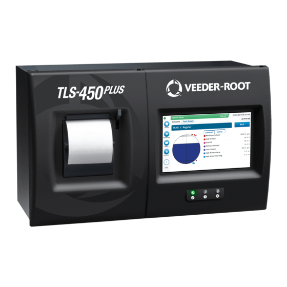
Veeder-Root TLS-450PLUS Module Replacement Instructions
Hide thumbs
Also See for TLS-450PLUS:
- User manual ,
- Troubleshooting manual (127 pages) ,
- Install, setup, & operation manual (98 pages)
Summary of Contents for Veeder-Root TLS-450PLUS
- Page 1 Manual No: 577014-077 Revision: D ● TLS-450PLUS Console Module Replacement Instructions...
- Page 2 If “lost” equipment is delivered at a later date and is not needed, Veeder-Root will allow a Return to Stock without a restocking fee. Veeder-Root will NOT be responsible for any compensation when a customer chooses their own carrier.
-
Page 3: Table Of Contents
Figure 1. USB Module - USB ports ................3 Figure 2. DB Backup Screen .................4 Figure 3. TLS-450PLUS Console Plug-In Module Bays ........5 Figure 4. Opening The TLS-450PLUS Console Doors ..........7 Figure 5. Attaching ATM Pressure Board Onto USM Module ........9 Figure 6. -
Page 4: Related Manuals
If site preparation is necessary, refer to the TLS-450PLUS Site Prep and Installation manual, or contact your Veeder-Root representative for assistance. Also included in this manual is the procedure for upgrading software features. -
Page 5: Contractor Certification Requirements
Contractor Certification Requirements Contractor Certification Requirements Veeder-Root requires the following minimum training certifications for contractors who will install and setup the equipment discussed in this manual: Installer Certification (Level 1): Contractors holding valid Installer Certification are approved to perform wiring and conduit routing;... -
Page 6: Precautions Against Static Electricity
Before powering off the console perform a system backup: 1. Beneath the left side of the TLS-450PLUS console, locate the USB module and insert the V-R Backup thumb drive, minimum 4 GB, (P/N 332970-004) into one of the external USB ports, P/N 333477-001 (see item 3 in Figure 1). -
Page 7: Figure 2. Db Backup Screen
> Software Maintenance> DB Backup to view the Database Backup Screen (see Figure 2). Touch the down arrow in the Backup Destination field to select the Backup thumb drive inserted in Step 1, then follow the on-screen instructions to backup TLS-450PLUS console data. System Status... -
Page 8: Console Module Locations
1, 2, 3 or 4 Pressure Board I/O Module Port 1 MDIM LVDIM Port 2 4 Only 10 Amp Controller 1 2 3 955-1.eps User-Selectable Comm Fixed Comm Case of console Module slots Module slots Figure 3. TLS-450PLUS Console Plug-In Module Bays... -
Page 9: Console Comm Modules
Console Module Locations Console Comm Modules Console Comm Modules Table 3 lists optional comm modules, their permissible slots in the comm bay and the configurable (C) and non- configurable (NC) ports for each module in each slot. Slots 4 (Ethernet module) and 5 (USB module) are fixed and are unavailable for user-selectable Comm modules. Table 3. -
Page 10: Module Removal/Installation
Module Removal/Installation Removing An Interface Module Disconnect, tag and lockout power to the TLS-450PLUS console be- WARNING fore starting this procedure. 3. Remove the both left and right door screws (with a T-15 Torx driver) and swing open both doors to the left (see Figure 4). -
Page 11: Installing A Usm Module
Try not to have too much wire in the console. Pull unneeded wire back into the wiring trough and loop it neatly. The TLS-450PLUS doesn’t have pre-assigned slots for the Interface Modules so any of the four slots can accommodate intrinsically safe (USM) or non-intrinsically safe (I/O, MDIM, etc.) Interface Modules (see Figure 3). -
Page 12: Installing An Atm Pressure Board Onto A Usm Module
Torx head screws. 9. Close the console’s front doors, reversing the procedure in Step 2 above. 10.Power up the TLS-450PLUS console and perform a DB Restore, then setup the newly installed ATM Pressure Sensor using the TLS-450PLUS Online help. Figure 5. Attaching ATM Pressure Board Onto USM Module... -
Page 13: Installing An I/O, Mdim, Lvdim Or 10 Amp Controller Interface Module
Intrinsically-safe wiring cannot enter a I/O, MDIM, LVDIM or 10 Amp Controller mod- WARNING ule’s slot knockout. Disconnect, tag and lockout power to the TLS-450PLUS console be- WARNING fore starting this procedure. 1. Referencing Figure 4, open the left and right doors of the console. -
Page 14: Installing A Comm Module
Module Removal/Installation Installing A Comm Module Installing A Comm Module Disconnect, tag and lockout power to the TLS-450PLUS console be- WARNING fore starting this procedure. 1. Referencing Figure 4, open the left and right doors of the console. 2. The Comm Bay is divided into 5 communication slots numbered from 1 to 5 going left to right (see Figure 3). -
Page 15: Installing Software Features
Installing Software Features Before installing a software feature upgrade, perform a system backup using a V-R Backup thumb drive (P/N 332970-004) following the procedure described in “Before Turning Off Power” on page 3. The V-R Backup thumb drive is different from a V-R Software Upgrade thumb drive - the two NOTICE are not interchangeable. - Page 16 For technical support, sales or other assistance, please visit: www.veeder.com...


Need help?
Do you have a question about the TLS-450PLUS and is the answer not in the manual?
Questions and answers