Table of Contents
Advertisement
Quick Links
UM_1904_PL88_1910_133036
About this document
Scope and purpose
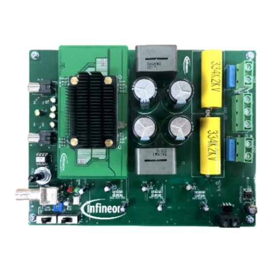
The EVAL_AUDAMP24 GaN e-mode High Electron Mobility Transistor (HEMT) evaluation board is a two-channel,
225 W/ch (4 Ω at ±43 V) or 250 W/ch (8 Ω at ±63 V) half-bridge class D audio power amplifier for Hi-Fi audio
systems. This evaluation board demonstrates how to use the CoolGaN™ gallium nitride transistor, IRS20957S
controller IC, implement protection circuits, and design an optimum PCB layout using the IGT40R070D1 E8220,
CoolGaN™ gallium nitride transistor. The reference design provides all the required housekeeping power
supplies for ease of use. The two-channel design is scalable for power and the number of channels.
Applications
Hi-Fi amplifiers
AV receivers
Home theater systems
Powered speakers
Musical instrument amplifiers
Features
Output power:
225 W x 2 channels (1 percent THD+N, 4 Ω at ±43 V)
−
250 W x 2 channels (1 percent THD+N, 8 Ω at ±63 V)
−
Multiple protection features:
Over-Current Protection (OCP), high-side and low-side CoolGaN™ transistors
−
Over-Voltage Protection (OVP)
−
Under-Voltage Protection (UVP), high-side and low-side CoolGaN™ transistors
−
Over-Temperature Protection (OTP)
−
PWM modulator:
Self-oscillating half-bridge topology with optional clock synchronization
−
Table of contents
About this document ....................................................................................................................... 1
Table of contents ............................................................................................................................ 1
1
Specifications ........................................................................................................................ 3
2
EVAL_AUDAMP24 overview ...................................................................................................... 4
3
Setup guide ........................................................................................................................... 6
3.1
Typical connections ................................................................................................................................ 6
4
Connector description ............................................................................................................ 7
5
Audio analyzer setup .............................................................................................................. 8
6
Operating the evaluation board ............................................................................................... 9
User Manual
www.infineon.com/eval-audamp24
page 1 of 53
V 1.0
2020-03-19
Advertisement
Table of Contents

Related Manuals for Infineon EVAL_AUDAMP24


Summary of Contents for Infineon EVAL_AUDAMP24
-
Page 1: Table Of Contents
Scope and purpose The EVAL_AUDAMP24 GaN e-mode High Electron Mobility Transistor (HEMT) evaluation board is a two-channel, 225 W/ch (4 Ω at ±43 V) or 250 W/ch (8 Ω at ±63 V) half-bridge class D audio power amplifier for Hi-Fi audio systems. - Page 2 EVAL_AUDAMP24 IRS20957SPBF + IGT40R070D1 E8220 evaluation board Table of contents Test setup ..............................9 Power-up sequence..........................9 Audio functionality tests ......................... 9 External clock function ........................... 9 Power-down sequence ......................... 10 Audio performance ........................ 11 Power vs. THD+N ........................... 11 Frequency response ..........................
-
Page 3: Specifications
EVAL_AUDAMP24 IRS20957SPBF + IGT40R070D1 E8220 evaluation board Specifications Specifications Table 1 General test conditions Condition Notes/conditions Supply voltages ±38 V ~ ±75 V Bipolar power supply Rated load impedance 4 to 8 Ω Resistive load Self-oscillating frequency 500 kHz No input signal, adjustable... -
Page 4: Eval_Audamp24
EVAL_AUDAMP24 overview EVAL_AUDAMP24 overview The EVAL_AUDAMP24 features a two-channels self-oscillating type PWM modulator for the lowest component count, highest performance and robust design. This topology represents an analog version of a second-order sigma-delta modulation, having a class D switching stage inside the loop. The benefit of the sigma-delta modulation, in comparison to the carrier-signal based modulation, is that all the error in the audible frequency range is shifted to the inaudible upper-frequency range by nature of its operation. - Page 5 EVAL_AUDAMP24 IRS20957SPBF + IGT40R070D1 E8220 evaluation board EVAL_AUDAMP24 overview Feedback Daughter-board Integrator IGT40R070D 1 Direct-FET IRS20957S Gate Driver Figure 2 Simplified block diagram of class D amplifier User Manual 5 of 53 V 1.0 2020-03-19...
-
Page 6: Setup Guide
EVAL_AUDAMP24 IRS20957SPBF + IGT40R070D1 E8220 evaluation board Setup guide Setup guide Typical connections 38 to 75 V, 8 A DC supply 38 to 75 V, 8 A DC supply 4 ~ 8 Ω or 4 ~ 8 Ω or speaker... -
Page 7: Connector Description
EVAL_AUDAMP24 IRS20957SPBF + IGT40R070D1 E8220 evaluation board Connector description Connector description Table 4 Connector description CH1 IN Analog input for CH1 CH2 IN Analog input for CH2 POWER Positive and negative supply (+B/-B) CH1 OUT Output for CH1 CH2 OUT... -
Page 8: Audio Analyzer Setup
EVAL_AUDAMP24 IRS20957SPBF + IGT40R070D1 E8220 evaluation board Audio analyzer setup Audio analyzer setup Figure 4 Audio analyzer connection User Manual 8 of 53 V 1.0 2020-03-19... -
Page 9: Operating The Evaluation Board
EVAL_AUDAMP24 IRS20957SPBF + IGT40R070D1 E8220 evaluation board Operating the evaluation board Operating the evaluation board Test setup 1. Connect 4 or 8 Ω 250 W dummy loads to output connectors (J1 and J5 as shown in Figure 3) and parallel it with input of the Audio Precision (AP) analyzer. -
Page 10: Power-Down Sequence
EVAL_AUDAMP24 IRS20957SPBF + IGT40R070D1 E8220 evaluation board Operating the evaluation board Power-down sequence 14. Turn-off ± power supply at the same time. 15. All LEDs turn-off when housekeeping power supplies are off. User Manual 10 of 53 V 1.0 2020-03-19... -
Page 11: Audio Performance
EVAL_AUDAMP24 IRS20957SPBF + IGT40R070D1 E8220 evaluation board Audio performance Audio performance Power vs. THD+N Test conditions: = ± 43 V Input signal = 1 kHz Load impedance = 4 Ω = 500 kHz dx=-279.3 W dy=-10.2395 % 10.2748 0.05 0.0353 0.02... -
Page 12: Frequency Response
EVAL_AUDAMP24 IRS20957SPBF + IGT40R070D1 E8220 evaluation board Audio performance Test conditions: = ± 63 V Input signal = 1 kHz Load impedance = 8 Ω = 500 kHz 0.05 0.02 0.01 0.005 0.002 0.001 100m 200m 500m Sweep Trace Color... - Page 13 EVAL_AUDAMP24 IRS20957SPBF + IGT40R070D1 E8220 evaluation board Audio performance 100k 200k Sweep Trace Color Line Style Thick Data Axis Comment Solid Anlr.Level A Left Figure 7 Frequency response 4 Ω load Test conditions: = ± 63 V Output power = 1 W Load impedance = 8 Ω...
-
Page 14: Noise Floor
EVAL_AUDAMP24 IRS20957SPBF + IGT40R070D1 E8220 evaluation board Audio performance Noise floor Test conditions: = ±43 V No input signal Load impedance = 4 Ω = 500 kHz -100 -110 -120 -130 -140 -150 Sweep Trace Color Line Style Thick Data... -
Page 15: Noise Floor With 1 V
EVAL_AUDAMP24 IRS20957SPBF + IGT40R070D1 E8220 evaluation board Audio performance -100 -110 -120 -130 -140 -150 Sweep Trace Color Line Style Thick Data Axis Comment Blue Solid Fft.Ch.1 Ampl Left Solid Fft.Ch.2 Ampl Left Figure 10 Noise floor 8 Ω load... - Page 16 EVAL_AUDAMP24 IRS20957SPBF + IGT40R070D1 E8220 evaluation board Audio performance Test conditions: = ± 63 V Output = 1 V at 1 kHz Load impedance = 8 Ω = 500 kHz -100 -110 Sweep Trace Color Line Style Thick Data Axis...
-
Page 17: Functional Descriptions
MOSFET with its very low on-resistance, very high speed and clean switching capabilities. Figure 13 Internal structure of Infineon’s CoolGaN™ The basic structure of a GaN FET is similar to a silicon MOSFET, with gate, source and drain terminals. The heart of the GaN switch is a lateral two-dimensional electron gas (2DEG) layer formed in the GaN layer. - Page 18 Figure 14 is the class D switching stage using a GaN FET, Infineon IGT40R070D1 E8220. Using a GaN FET takes a different gate-drive scheme. A silicon MOSFET receives 0 V or 10 V gate voltage with respect to the source to turn the switch off and on.
-
Page 19: Power Supply
Overall regulation and output voltage ripple for the power supply design are not critical when using the EVAL_AUDAMP24 class D amplifier as the Power Supply Rejection Ratio (PSRR) of the EVAL_AUDAMP24 is excellent (Figure 15). -
Page 20: Housekeeping Power Supply
LPF, causing a large reactive current flowing through the switching stage, and the LC resonance can activate OCP. The EVAL_AUDAMP24 has an RC network called a Zobel network (R45 and C36) to damp the resonance and prevent peaking frequency response with light loading impedance. -
Page 21: Efficiency
(250 W into 8 ). 8.10 Efficiency Figures 17 and 18 show efficiency characteristics of the EVAL_AUDAMP24. The high efficiency is achieved by the following factors: Low conduction loss due to the CoolGaN™offering low R ... -
Page 22: Output Filter Design And Preamplifier
LPF. Since the output filter is not included in the control loop of the EVAL_AUDAMP24, the reference design cannot compensate for performance deterioration due to the output filter. Therefore, it is important to understand what characteristics are preferable when designing the output filter: The DC resistance of the inductor should be minimal and within 20 mΩ... -
Page 23: Switches And Indicators
“click noise”, although in some cases, it can be louder than the click noise of non- relay-based solutions. The EVAL_AUDAMP24 does not use any series relay to disconnect the speaker from the audible transient noise, but rather a shunt-based click-noise reduction circuit that yields audible noise levels that are far less that those generated by the relays they replace. -
Page 24: Click And Pop Noise Reduction
8.17 Start-up and shutdown sequencing The EVAL_AUDAMP24 sequencing is achieved through the charging and discharging of the CStart capacitor C66. This, coupled to the charging and discharging of the voltage of CSD (C11 on daughter board for CH1) of the IRS20957SPBF, is all that is required for complete sequencing. - Page 25 EVAL_AUDAMP24 IRS20957SPBF + IGT40R070D1 E8220 evaluation board Functional descriptions CStart Ref1 CStart Ref2 CSD= 2/3 V CStart +5 V Time -5 V UVP@-20 V CHx_O SP MUTE Audio MUTE Class D startup Music startup Figure 20 Conceptual start-up sequencing of power supplies and audio section timing For start-up sequencing, ±B supplies start up at different intervals.
-
Page 26: Selectable Dead-Time
EVAL_AUDAMP24 IRS20957SPBF + IGT40R070D1 E8220 evaluation board Functional descriptions Shutdown sequencing is initiated once UVP is activated. As long as the supplies do not discharge too quickly, the shutdown sequence can be completed before the IRS20957SPBF trips UVP. Once UVP is activated, CSD and CStart are discharged at different rates. -
Page 27: Protection System Overview
EVAL_AUDAMP24 IRS20957SPBF + IGT40R070D1 E8220 evaluation board Functional descriptions 0.23xVcc 0.36xVcc 0.57xVcc Figure 23 Dead-time setting vs. V voltage 8.19 Protection system overview The IRS20957SPBF integrates OCP inside the IC. The rest of the protections, such as OVP, UVP and OTP, are detected externally to the IRS20957SPBF. -
Page 28: High-Side Current Sensing
EVAL_AUDAMP24 IRS20957SPBF + IGT40R070D1 E8220 evaluation board Functional descriptions The voltage setting on the OCSET pin programs the threshold for low-side over-current sensing. When the VS voltage becomes higher than the OCSET voltage during low-side conduction, the IRS20957SPBF turns the outputs off and pulls CSD down to –VSS. -
Page 29: Over-Voltage Protection (Ovp)
EVAL_AUDAMP24 IRS20957SPBF + IGT40R070D1 E8220 evaluation board Functional descriptions Figure 26 Simplified functional block diagram of high-side current sensing 8.19.2 Over-Voltage Protection (OVP) OVP is provided externally to the IRS20957SPBF. OVP shuts down the amplifier if the bus voltage between GND and -B exceeds 82 V. -
Page 30: Offset Null (Dc Offset) Adjustment
IRS20957SPBF + IGT40R070D1 E8220 evaluation board Functional descriptions 8.19.5 Offset null (DC offset) adjustment The EVAL_AUDAMP24 is designed such that no output-offset nullification is required. DC offsets are tested to be less than ±5 mV. 8.19.6 Over-Temperature Protection (OTP) A separate PTC resistor is placed in close proximity to the high-side IGT40R070D1 E8220 CoolGaN for each of the amplifier channels. - Page 31 EVAL_AUDAMP24 IRS20957SPBF + IGT40R070D1 E8220 evaluation board Functional descriptions Figure 28 Peak power P = 250 W with 8 Ω load ±63 V Note: Maximum temperature 72.5°C at 1 minute. Table 8 1/8 power test Load (Ω) ±V Max. T-case (°C)
- Page 32 EVAL_AUDAMP24 IRS20957SPBF + IGT40R070D1 E8220 evaluation board Functional descriptions Figure 30 1/8 power = 31.25 W with 8 Ω load ±63 V Note: Maximum temperature 85.5°C at 30 minutes, room temperature = 25°C. User Manual 32 of 53 V 1.0...
-
Page 33: Thermal Interface Materials (Tims)
EVAL_AUDAMP24 IRS20957SPBF + IGT40R070D1 E8220 evaluation board Functional descriptions 8.20.2 Thermal Interface Materials (TIMs) Recommend TIMs for heatsink attachment. Figure 31 TIM recommendations User Manual 33 of 53 V 1.0 2020-03-19... -
Page 34: Schematic
EVAL_AUDAMP24 IRS20957SPBF + IGT40R070D1 E8220 evaluation board Schematic Schematic Figure 32 Motherboard schematic 1 User Manual 34 of 53 V 1.0 2020-03-19... - Page 35 EVAL_AUDAMP24 IRS20957SPBF + IGT40R070D1 E8220 evaluation board Schematic Figure 33 Motherboard schematic 2 User Manual 35 of 53 V 1.0 2020-03-19...
- Page 36 EVAL_AUDAMP24 IRS20957SPBF + IGT40R070D1 E8220 evaluation board Schematic Figure 34 Motherboard schematic 3 User Manual 36 of 53 V 1.0 2020-03-19...
- Page 37 EVAL_AUDAMP24 IRS20957SPBF + IGT40R070D1 E8220 evaluation board Schematic Figure 35 Motherboard schematic 4 User Manual 37 of 53 V 1.0 2020-03-19...
- Page 38 EVAL_AUDAMP24 IRS20957SPBF + IGT40R070D1 E8220 evaluation board Schematic Figure 36 Daughter board schematic User Manual 38 of 53 V 1.0 2020-03-19...
-
Page 39: Pcb
EVAL_AUDAMP24 IRS20957SPBF + IGT40R070D1 E8220 evaluation board 10.1 PCB specification 1. Two-layer SMT PCB with through-holes 2. 1/16 thickness 3. 2/0 oz. Cu 4. FR4 material 5. 20 mil lines and spaces 6. Solder mask to be green enamel EMP110 DBG (CARAPACE) or Enthone endplate DSR-3241 or equivalent 7. -
Page 40: Pcb Layout
EVAL_AUDAMP24 IRS20957SPBF + IGT40R070D1 E8220 evaluation board 10.2 PCB layout Figure 37 Motherboard top view User Manual 40 of 53 V 1.0 2020-03-19... - Page 41 EVAL_AUDAMP24 IRS20957SPBF + IGT40R070D1 E8220 evaluation board Figure 38 Motherboard bottom view User Manual 41 of 53 V 1.0 2020-03-19...
- Page 42 EVAL_AUDAMP24 IRS20957SPBF + IGT40R070D1 E8220 evaluation board Figure 39 Daughter board top view Figure 40 Daughter board bottom view User Manual 42 of 53 V 1.0 2020-03-19...
-
Page 43: Bill Of Materials (Bom)
EVAL_AUDAMP24 IRS20957SPBF + IGT40R070D1 E8220 evaluation board Bill of Materials (BOM) Bill of Materials (BOM) Table 9 Motherboard BOM Part number Designator Description Quantity Vendor C1, C33, C50, C75, Capacitor 10 µF 50 V 565-1106-ND elect. SMG RAD Digikey Capacitor 10 µF 16 V... - Page 44 EVAL_AUDAMP24 IRS20957SPBF + IGT40R070D1 E8220 evaluation board Bill of Materials (BOM) Part number Designator Description Quantity Vendor Ceramic capacitor AMIC PCC2009CT-ND C38, C42, C56, C60 1000 pF 200 V NP0 1206 Digikey Capacitor 2.2 µF 16 V PCC1931CT-ND C39, C57...
- Page 45 EVAL_AUDAMP24 IRS20957SPBF + IGT40R070D1 E8220 evaluation board Bill of Materials (BOM) Part number Designator Description Quantity Vendor Fast diode rec. 200 V 1 A RS1DB-FDICT-ND Digikey Conn. term. block 2-pos. 277-1271-ND J1, J5 9.52 mm PCB Digikey Conn. recept. 6-pos .100 A26453-ND vert.
- Page 46 EVAL_AUDAMP24 IRS20957SPBF + IGT40R070D1 E8220 evaluation board Bill of Materials (BOM) Part number Designator Description Quantity Vendor R2, R3, R5, R7, R84, Resistor 10 kΩ 1/8 W 5 P10KACT-ND R92, R99 percent 0805 SMD Digikey Resistor 20 kΩ 1/8 W 5...
- Page 47 EVAL_AUDAMP24 IRS20957SPBF + IGT40R070D1 E8220 evaluation board Bill of Materials (BOM) Part number Designator Description Quantity Vendor R50, R75, R80, R90, Resistor 100 Ω 1/4 W 5 P100ECT-ND percent 1206 SMD Digikey R51, R52, R76, R77, R104, R106, R121, Resistor 1.0 kΩ 1/8 W 5 P1.0KACT-ND...
- Page 48 EVAL_AUDAMP24 IRS20957SPBF + IGT40R070D1 E8220 evaluation board Bill of Materials (BOM) Part number Designator Description Quantity Vendor Slide switch DP3T 0.2 A L EG1944-ND S1, S2 = 6 mm Digikey 6 mm light touch SW H = P8010S-ND Digikey IC reg. buck 75 V 0.5 A...
- Page 49 EVAL_AUDAMP24 IRS20957SPBF + IGT40R070D1 E8220 evaluation board Bill of Materials (BOM) Table 10 Daughterboard BOM Part number Designator Description Quantity Vendor Ceramic capacitor 47000 pF 100 V X7R 10 445-2276-1-ND C1A, C1B, C3A, C3B percent 0805 Digikey Capacitor 47 pF 50 V...
- Page 50 EVAL_AUDAMP24 IRS20957SPBF + IGT40R070D1 E8220 evaluation board Bill of Materials (BOM) Part number Designator Description Quantity Vendor Conn. recept. 8-pos .100 SAM1030-04-ND vert. dual Digikey 732-5296-ND Substitute for J3 Transistor 160 V 300 MMBT5551-7DICT-ND Q1A, Q1B mW NPN SMD SOT-23...
- Page 51 EVAL_AUDAMP24 IRS20957SPBF + IGT40R070D1 E8220 evaluation board Bill of Materials (BOM) Part number Designator Description Quantity Vendor R23A, R23B, R25A, Resistor SMD 560 Ω 1 311-560HRCT-ND R25B percent 0.1 W 00603 Digikey R24A, R24B, R26A, Resistor SMD 15 Ω 1...
- Page 52 EVAL_AUDAMP24 IRS20957SPBF + IGT40R070D1 E8220 evaluation board Revision history Revision history Document Date of release Description of changes version V 1.0 2020-03-19 First release User Manual 52 of 53 V 1.0 2020-03-19...
- Page 53 With respect to any examples, hints or any typical 81726 Munich, Germany values stated herein and/or any information WARNINGS regarding the application of the product, Infineon Technologies hereby disclaims any and all Due to technical requirements products may contain warranties and liabilities of any kind, including dangerous substances.
Need help?
Do you have a question about the EVAL_AUDAMP24 and is the answer not in the manual?
Questions and answers