Table of Contents
Advertisement
Quick Links
Advertisement
Table of Contents

Related Manuals for golmar IP 6502/G+


Summary of Contents for golmar IP 6502/G+
- Page 1 6502/G+ 12327402 (Manual based on FW version 1.04)
-
Page 2: Table Of Contents
..............................3 3. Panel description 4. Panel installation ................................4 5. Initial configuration ..............................5 6. Initial alternative configuration through web client ....................6 7. Settings ................................... 8 8. System operation ................................9 9. Installation diagram ..............................10 Footer Infos www.golmar.es... -
Page 3: Safety Cautions And Warnings
N.O, N.C door release dry contacts Local power supply input +12V (*) Anti-vandal tamper. (**) In case to power the panel with a local power supply, the ethernet cable cannot be connected to a PoE output of the distributor D4L-G+. www.golmar.es... -
Page 4: Panel Installation
5- Fix the bottom part of the panel using the screws supplied. 6- Slide up the header supplied, to cover the bottom part of the panel and tight the screws underneath. (*) Header screw should be tight using the supplied tool. www.golmar.es... -
Page 5: Initial Configuration
Enter the IP Server address. the panel and press validation validation icon. It is IP address of the system validation icon. manager panel. icon. Once all the steps have been completed, will appear the same confirmation screen as in automatic option. www.golmar.es... -
Page 6: Initial Alternative Configuration Through Web Client
Select Internet Enter into “properties”. Set the IP range. protocol IPv4. IP address should start by 10. Next three numbers should have a value lower than 255. Assign 10.0.0.1 as Gateway. Do not assign DNS Confirm settings. Footer Infos www.golmar.es... - Page 7 You also will be able to enable or disable prompt messages and set the **Prompt modes 4 English 7 Portuguese 0 OFF language in which they are reproduced. 1 Spanish 5 French 8 Ring tones 2 Danish 6 Greek Previous NOTE: For more information about web client, visit its manual. www.golmar.es...
-
Page 8: Settings
The screen will display “card added”. A maximum of 5 cards per apartment can be (*) It is possible to delete or transfer the cards to other panels. To proceed, select the option in the step 5. Footer Infos www.golmar.es www.golmar.es... -
Page 9: System Operation
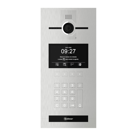
En comunicación Comunicación nalizada (*) The push button allows to make a direct call to the available guard units. 09:27 20-09-2017 ACCESS ADDRESS CODE CODE OPEN DOOR PROXIMITY Marcar el número de vivienda o pulsar para mostrar la agenda www.golmar.es... - Page 10 Access to the fourth option Choose between the four available options: Disable, Lock 1 only, Lock 2 “Unlock with access code” only or Lock 1 and 2. During a door release process, the panel will display on screen “Door is open”. Puerta abierta www.golmar.es...
-
Page 11: Installation Diagram
6502/G+ CATEGORY 1_HEADER CATEGORY 2_HEADER IP G+ 9. INSTALLATION DIAGRAM COLUMN POWER LOCAL POWER TERMINAL BLOCK 6502/G+ TERMINAL BLOCK CONNECTION Power up the D4L-G+/POE switches with the FA-G+, 18Vdc power supply unit.. Each switch can be powered locally, by connecting the terminals “+” and “-” to the power supply. The Jumper positicion of the switch must be as follow: It can be also powered through the riser from OUT terminal at the switch placed just before . - Page 12 Sistemas de comunicación S.A. C/ Silici 13. Poligon Industrial Famadas 08940 – Cornellà del llobregat – Spain golmar@golmar.es Telf: 934 800 696 www.golmar.es Golmar reserves the right to make any changes without prior notice.
Need help?
Do you have a question about the IP 6502/G+ and is the answer not in the manual?
Questions and answers