Advertisement
Available languages
Available languages
Quick Links
Advertisement

Related Manuals for golmar 6502/G+


Summary of Contents for golmar 6502/G+
- Page 1 6502/G+ 12327402 GUÍA RÁPIDA 6502/G+ V05 REV.0121|ESPAÑOL...
-
Page 2: Table Of Contents
2. Características ................................3 3. Descripción de la placa ..............................3 4. Instalación de la placa ..............................4 5. Configuración inicial ..............................5 6. Ajustes .................................... 6 7. Funcionamiento del sistema ............................7 8. Esquema de instalación ............................... 8 www.golmar.es... -
Page 3: Precauciones De Seguridad
- Bornes de conexión Conector RJ-45 Entrada para pulsador exterior Contacto N.A o N.C de apertura de puerta para electrocerradura 2 Contacto N.A o N.C para electrocerradura 1 Alimentación local +12V (*) Tamper antisabotaje junto a los bornes de conexión. www.golmar.es... -
Page 4: Instalación De La Placa
6- Inserte, de abajo hacia arriba, el cabezal suministrado para suministrados: cubrir la parte inferior de la placa (1), y finalmente fije el tornillo de la parte inferior del cabezal (2): (*) Realice la fijación del cabezal con la herramienta suministrada. www.golmar.es... -
Page 5: Configuración Inicial
Dirección Mac (*) Vea la guía rápida del monitor para conocer la configuración que deberá tener este para comunicarse con la placa. (**) Cuando la placa se encuentre en reposo (pantalla apagada), será necesario pulsar cualquier tecla para poder interactuar. www.golmar.es... -
Page 6: Ajustes
Hasta un máximo de 5 tarjetas por vivienda seleccionada presione validar nos mostrara “tarjeta registrada” (*) Es posible realizar un borrado o duplicado siguiendo la misma dinámica, para ello deberá seleccionar en el paso 5 la opción respectivamente. www.golmar.es... -
Page 7: Funcionamiento Del Sistema
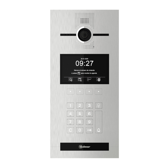
Marcar el número de vivienda o pulsar para mostrar la agenda En apertura, ya bien sea por código o proximidad, la placa nos alertará con un mensaje de voz indicando “Puerta abierta” y mostrará en pantalla “Puerta abierta”. Puerta abierta www.golmar.es... -
Page 8: Esquema De Instalación
El nº máximo de dispositivos que puede alimentar la FA-G+ es de 8 monitores o 4 placas de calle. Por lo que se necesitará un alimentador por cada 8 dispositivos. El abrepuertas a conectar podrá ser de alterna (necesario transformador de 12Vca, recomendado TF-104) o de continua (necesario transformador de 12Vcc, recomendado HRF-12/1,25A). www.golmar.es... - Page 9 Sistemas de comunicación S.A. C/ Silici 13. Poligon Industrial Famadas 08940 – Cornellà del llobregat – Spain golmar@golmar.es Telf: 934 800 696 www.golmar.es...
- Page 10 6502/G+ 12327402 QUICK GUIDE 6502/G+ V05 REV.0121|ENGLISH...
- Page 11 IP G+ CE-G+ INDEX ..........................3 Safety cautions and warnings ................................3 Specifications ..............................3 Panel description ..............................4 Panel installation .............................5 Initial configuration ................................. Settings ..............................7 System operation .............................8 Installation diagram www.golmar.es...
- Page 12 Door panel fixation Light sensor Header Screw to fix the header - Connections terminal block. RJ-45 conector NO, NC door release Exit button dry contacts. N.O, N.C door release dry contacts Local power supply input +12V (*) Anti-vandal tamper. www.golmar.es...
- Page 13 5- Fix the bottom part of the panel using the screws supplied. 6- Slide up the header supplied, to cover the bottom part of the panel and tight the screws underneath. (*) Header screw should be tight using the supplied tool. www.golmar.es...
- Page 14 (*) Check the quick guide of the monitor to know the monitor’s configuration, in order to communicate with the panel. (**) When the panel is in idle state, it will be necessary to push any button to wake it up. www.golmar.es...
- Page 15 Maximum 5 cards per apartment can be. validate button. The screen will display “card added”. (*) It is possible to delete or duplicate cards following the same procedure. To proceed, select the option in the step 5. www.golmar.es...
- Page 16 09:27 20-09-2017 ACCESS ADDRESS CODE CODE OPEN DOOR PROXIMITY Marcar el número de vivienda o pulsar para mostrar la agenda During a door release process, the panel will display on screen “Door is open”. Puerta abierta www.golmar.es...
- Page 17 It is required one power supply FA-G+ for every 8 devices. The door lock to be connected could be an AC lock (AC transformer will be necessary, recommended TF-104) or a DC lock ( DC power supply will be necessary, recommendedHRF-12/1,25A). www.golmar.es...
- Page 18 Sistemas de comunicación S.A. C/ Silici 13. Poligon Industrial Famadas 08940 – Cornellà del llobregat – Spain golmar@golmar.es Telf: +34 934 800 696 www.golmar.es...
Need help?
Do you have a question about the 6502/G+ and is the answer not in the manual?
Questions and answers