Table of Contents
Advertisement
Advertisement
Table of Contents

Related Manuals for golmar Tekna Plus SE


Summary of Contents for golmar Tekna Plus SE
- Page 1 TECHNOLOGY TEKNA PLUS SE MONITOR Code 50123594 REV.0 1 TEKNA PLUS SE...
-
Page 2: Table Of Contents
TEKNA PLUS SE MONITOR INTRODUCTION First of all, we thank and congratulate you for purchasing this product manufactured by Golmar. Our commitment to achieving the satisfaction of customers like you is manifested through our ISO-9001 certification and the manufacture of products like the one you have just purchased. -
Page 3: Characteristics
TEKNA PLUS SE MONITOR CHARACTERISTICS Monitor for Plus / Uno installation. 3.5” TFT colour screen Monitor with 3 common wires plus coaxial cable Monitor with 4 common wires plus twisted pair. Monitor with UTP cabling plus RJ-45 connector. Function and advanced programming buttons (to customise the monitor's functions). -
Page 4: Description Of The Monitor
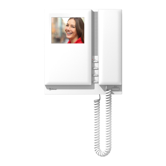
TEKNA PLUS SE MONITOR DESCRIPTION OF THE MONITOR Description of the Tekna Plus SE monitor: REF. TEKNA PLUS SE CODE 11742105 00000000000 INTER SLAVE MASTER CODE ATENCIÓN ESCALERA PISO PUERTA Alta tensión. No abrir la tapa. Manipular sólo por personal... -
Page 5: Function Push Buttons
" “ “ with the Tekna Plus SE monitor. This only functions if no call or communication is in progress. Regardless of the position of the handset, the auxiliary device is activated. With the handset hung up, the image from the door panel configured as master can be viewed (if busy... -
Page 6: Connector (Installation With Utp Cable)
TEKNA PLUS SE MONITOR DESCRIPTION OF THE MONITOR Description of the RJ-45 connector (installation with UTP cable): The monitor features an RJ-45 connector for installation with a UTP cable. It is located on the left-hand side of the back of the monitor. -
Page 7: Rctk-Plus Wall Mount Connection Block
TEKNA PLUS SE MONITOR DESCRIPTION OF THE WALL MOUNT CONNECTION BLOCK Description of the RCTK-PLUS wall mount connection block: CABLE Max. Max. pelado del cable. Max. câble dénudé. Max. peeled cable. Max. aanstrip lengte. 50mm. ( ) * Malla Malla... -
Page 8: Monitor Fixing
TEKNA PLUS SE MONITOR INSTALLATION OF THE MONITOR Fixing the monitor's wall mount connection block to the wall: Avoid dusty or smoky environments or locations near sources of heat. To fix the monitor directly to the wall, drill four Ø6mm holes and use the plugs and screws supplied. -
Page 9: Monitor Programming
TEKNA PLUS SE MONITOR PROGRAMMING THE MONITORS Programming the TEKNA PLUS SE monitor: Locate the SW2 DIP switch on the EL632 Plus sound module or the EL500SE microprocessor and set to ON. In systems with more than one door panel, only perform this procedure on the main door panel of each building. -
Page 10: Quick Monitor Programming
Once the programming has finished, set the programming switch to OFF. If this is not done, the door panel will emit tones to indicate that the system is still in programming mode. Quick programming of the Tekna Plus SE monitors: The SW2 DIP switch is located on the left-hand side of the back of the monitor. -
Page 11: Advanced Programming (Monitor Functions)
TEKNA PLUS SE MONITOR ADVANCED PROGRAMMING (MONITOR FUNCTIONS) Advanced programming of the functions of the Tekna Plus SE monitor: Advanced programming enables the monitor's default settings to be changed: Switch off the monitor to be programmed. Once switched off, press button for 3 seconds to enter "... -
Page 12: Men 2
Intercom with Tekna Plus monitors: Intercom with Tekna Plus SE monitors (default setting). If an apartment has Tekna Plus and Tekna Plus SE monitors, the Tekna Plus SE monitors should be configured with Intercom with Tekna Plus monitors mode, as Tekna Plus monitors do not allow an intercom call to a particular “... -
Page 13: Men 3
TEKNA PLUS SE MONITOR ADVANCED PROGRAMMING (MONITOR FUNCTIONS) Continued from the previous page. Men 3: Then adjust the settings as required: Repeating the ringtones: One repeat (default setting). To repeat the ringtone on the monitor: Each press on button selects a repeat of the “... -
Page 14: Men 4
TEKNA PLUS SE MONITOR ADVANCED PROGRAMMING (MONITOR FUNCTIONS) Continued from the previous page. Men 4: Then adjust the settings as required: " a ll the advanced monitor programming options " efault setting , Set to "default setting": Press button monitor... -
Page 15: Optional Connections
TEKNA PLUS SE MONITOR OPTIONAL CONNECTIONS Auxiliary device activation with Tekna Plus SE monitors: Auxiliary device activation requires the use of an SAR-12/24 relay unit. If the feature is shared by all monitors, connect their A1 terminals; if, however, each monitor has its own feature, use an SAR-12/24 relay for each one and do not connect their A1 terminals. -
Page 16: Intercom Within The Same Apartment
" intercom call mode is only available with the Tekna Plus SE monitor. This only functions if no call or communication is in progress. A number of audible tones emitted by the handset will confirm that the call is being made or that the unit being called is in communication with the door panel. -
Page 17: Push Button For Receiving Calls From The Apartment Front Door
Button for receiving calls from the apartment front door: The Tekna Plus SE monitor features as standard the ability to receive calls from the apartment front door. This feature precludes the need to use the bell by positioning a switch between terminals HZ— and — of the monitor “... -
Page 18: Wiring Diagrams
TEKNA PLUS SE MONITOR WIRING DIAGRAMS Video door entry system with coaxial cable: Remove the JP1 jumper from all of the distributors except the last. D4L-PLUS Mesh Mesh D4L-PLUS Mesh Mesh M =Master. Place this power supply as close as possible to the first distributor. -
Page 19: Wiring Diagrams
TEKNA PLUS SE MONITOR WIRING DIAGRAMS Video door entry system without coaxial cable: EL562 EL562 Remove the JP1 jumper from all of the distributors except the last D6L-Plus/2H EL562 EL562 D6L-Plus/2H M =Master. Place this power supply as close as possible to the first distributor. - Page 20 C/ Silici, 13 08940- Cornellá de Llobregat SPAIN Golmar se reserva el derecho a cualquier modificación sin previo aviso. Golmar se réserve le droit de toute modification sans préavis. Golmar reserves the right to make any modifications without prior notice.
Need help?
Do you have a question about the Tekna Plus SE and is the answer not in the manual?
Questions and answers