Table of Contents
Advertisement
Quick Links
FD80-H HEAVY DUTY SLIDING DOOR SYSTEM Installation Manual
(Surface mount roller Type for Pocket Door, with Two-way Soft Close)
Thank you for using our product. Before installation, please read this manual thoroughly to ensure correct installation.
Please keep this manual at hand for future reference.
ABOUT THE PRODUCT
This is a parts set for heavy duty sliding door system for
●
residential & commercial use.
B uilt in soft closer, enables two-way soft closing movement in
●
both direction.
T wo sections of track for easy maintenance after installing.
●
SPECIFICATIONS
Door height
Door width
Min. Door thickness
Max. Door weight
Vertical adjustmernt
・ The closing speed of the soft closing type door may change
depending on the ambient temperature, operating method or
installation quality.
・ R ecommended ambient temperature range is 5 to 40 ℃ .
1
When using a light weight door, you may feel the resistance
※
of the soft closer when opening the door.
FOR YOUR SAFETY AND CORRECT
Meaning of symbols
Warning
Caution
Warning :
If not followed, it may result in death or serious injury.
This product should be installed by a qualified person. If the system is not installed correctly, the door will not
operate smoothly, and may cause injury.
It is necessary to manufacture the frame with sufficient strength so that it endures the weight of the door and any impact
upon opening/closing the door. Only use designated screws and ensure that they are fastened firmly. A frame with poor
strength or loose screws might result in the door falling and causing injury
Do not use this product for any other purpose, or with doors that are outside the specifications of this manual.
Do not disassemble or modify any parts other than those described in this document.
Caution :
If not followed, it may result in injury or damage.
Make sure to follow the designated dimensions, specifications, and horizontal/vertical angles. Make sure that the frame and
door are not warped, since it may affect the movement of the door.
If cutting any parts, make sure to remove any burrs before installation. Also check the upper track for any left-over burrs or
scraps and remove these.
This product is a part for architectural fittings. After installation, make sure to test the finished product thoroughly to ensure
that it is functioning and safe. Please inform the end user how to use the product safely.
Make sure to check the screws for slack at regular intervals (one month from first usage, half a year, and then one time
every year is recommended).
When installing the "pocket door" specification, make an "easy-maintenance" structure.
For example, use a removable panel.
We recommend that the installation is carried out by two people, in order to ensure proper installation and avoid
unnecessary stress on the parts.
Max. 2500 mm
2501 – 2700 mm
784 – 1500 mm
850 – 1500 mm
30 mm
80 kg/door
± 4 mm
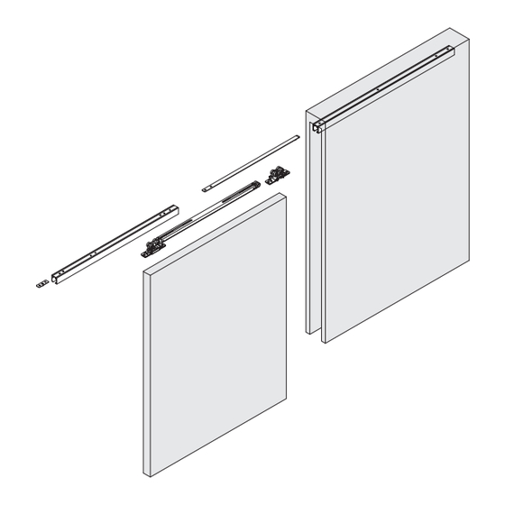
INSTALLATION
Prohibited
Required
Part No.FD80DHCMP-PD
Door pocket
Door
1
Advertisement
Table of Contents

Subscribe to Our Youtube Channel
Related Manuals for SUGATSUNE Lamp FD80-H


Summary of Contents for SUGATSUNE Lamp FD80-H
- Page 1 FD80-H HEAVY DUTY SLIDING DOOR SYSTEM Installation Manual (Surface mount roller Type for Pocket Door, with Two-way Soft Close) Part No.FD80DHCMP-PD Thank you for using our product. Before installation, please read this manual thoroughly to ensure correct installation. Please keep this manual at hand for future reference. ABOUT THE PRODUCT This is a parts set for heavy duty sliding door system for ●...
-
Page 2: Component Parts
COMPONENT PARTS ① ② ③ ④ ⑤ ⑥ ⑦ Trigger Soft Closer Name Upper track Front trigger Pocket trigger Upper roller Floor guide (two - way) Order code 250-022-240 250-036-530 250-029-709 250-029-708 250-022-242 250-029-718 Part No. FD80-TRP FD80-WRM-DSC FD80-TRG FD80-TRGPF FD80-TRGPB-MB FD80-WRM FD50-BGR18 Parts... -
Page 3: Closed Position
INSTALLATION DRAWING (EXAMPLE) The example shows the sliding door when the leading edge (at the fully opened position) is aligned with the connecting position of the upper tracks. To shift the connecting position towards the trailing edge, see page 11. Leading Trailing edge... -
Page 4: Installation Procedure
INSTALLATION PROCEDURE Cutting Track and Hole Drilling on Upper Track Caution Caution When cutting, reinforce the Do not cut the track on the track to prevent deformation side with three holes. at the cut section. When using 1260 mm track Connecting side Leading edge Track length for open area : Lo... - Page 5 Nounting of Door Pocket Track Caution Remove any dirt or aluminum chips from the track The end which has three Caution countersunk holes must ① Door pocket track face the center. Install the cover panel onto the door pocket after mounting the track. Attached screws (Countersunk head tapping screws 5 ×...
-
Page 6: Installing Bracket
Installing Bracket Installation of Door Guide Track 1 Cut the track to the same length as the door width. Fastening Disassemble Caution Pay attention to setting the direction of the bracket. The open part of the bracket should face in the outside direction. When cutting, reinforce Upper roller the track to prevent deformation... - Page 7 Mounting of Open Area Track. Caution 【1】 Connecting to door pocket track. Overlap the two countersunk holes on the pocket trigger and the two holes on Align the track end to the end of the the open area track. door pocket track. Deviation of the joint position makes ①Open area track insertion of the trigger difficult.
- Page 8 Mounting of Floor Guide Temporarily Position floor guide just below the Caution Temporarily fasten through the center of upper track. slotted holes with the provided The position of the model screws. where the margin occurs is 4 × 20 shown in the figure. (included in ⑦) Slotted hole Slotted hole...
- Page 9 Adjusting the Door Position Adjust door such that door is parallel to upper track with 6-14 mm clearance Pull out the holder between door and floor. Caution Upper roller Vertical adjustment Bracket Do not turn adjustment screw beyond range: 8 mm adjustment range.
- Page 10 Appendix 1 How to Remove Door, Track Hanger bolt 【1】 How to remove door (Leading edge) Put a 10 mm support under the door on the leading edge. Remove holder Pull out the Hanger bolt at leading edge from the Bracket. Pull out the door, while making sure not to let it scratch against the door pocket.
- Page 11 Appendix 2 How to Shift the Connecting Position of The Tracks. Put a mark on the 【1】 When determining the trigger position on site open area track with reference to (1) Put a mark on the Open area track with reference to the front the leading edge of end of the door at the fully opened position.
-
Page 12: Troubleshooting
SUGATSUNE AMERICA, INC Tokyo, JAPAN Shanghai, CHINA California, USA Phone: +81 (0)3 3866 2260 E-mail:export@sugatsune.co.jp Phone: +86 21 3632 1858 E-mail:lamp@sugatsune.com.cn Phone: +1 310 329 6373 E-mail:sales@sugatsune.com SUGATSUNE KOGYO (UK) LTD Guangzhou, CHINA Chicago, USA Reading, UK Phone: +86 20 6639 3552 E-mail:lamp@sugatsune.com.cn...
Need help?
Do you have a question about the Lamp FD80-H and is the answer not in the manual?
Questions and answers