
Related Manuals for AOR Trans.View AR570


Summary of Contents for AOR Trans.View AR570
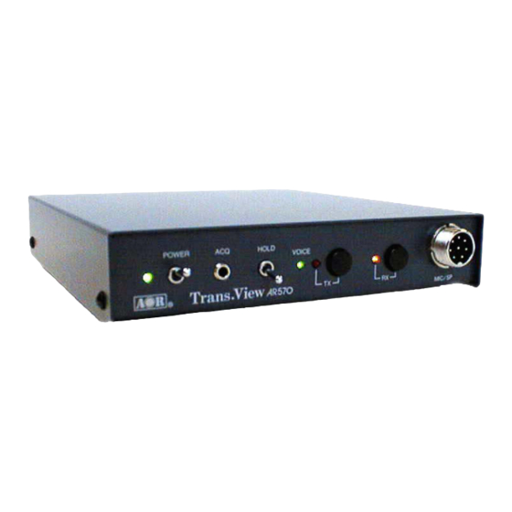
- Page 1 Stand Alone Color Image Facsimile System Trans.View AR570 MODEL: Operating Manual AOR, LTD.
-
Page 2: Table Of Contents
Table of Contents 1: Specifications 2: Introduction 2-1: General Description 2-2: Equipment List 2-3: Applications 3: Summary of Controls 3-1: Front Panel 3-2: Rear Panel 3-3: DIP Switches 3-3-1: Mode Switch (MODE-SW) 3-3-1-1: Operating Mode 3-3-1-2: RS232C communication speed and Automatic Dialing Transmission 3-3-2: Continuous Transmission and DTMF Remote Control Mode (AUTO-SW) 3-3-2-1: Continuous Transmission (for only operation via leased line) - Page 3 Extended Operation 6-1: Remote Control 6-1-1: Remote Control over leased line link 6-1-2: Remote Control over two-way Radio link 6-2: Full Automatic picture transmission control (use for only leased line) 6-2-1: One Transmission...
- Page 4 Consult the dealer or an experienced radio/TV technician for help. This manual is protected by copyright AOR, LTD. No information contained in this manual may be copied or transferred by any means without the prior written consent of AOR,LTD. Copyright ©1998 All rights reserved.
-
Page 5: 1: Specifications
1: Specifications Product AR570 Still Image Color Facsimile System. Operating Mode AOR original SCFM format and protocol Color 27, 69 second mode Black & White 18, 35 second mode Video Input/Output NTSC (or PAL) Asynchronous 4fs sampling/75Ω1v p-p ... -
Page 6: 2: Introduction
2: Introduction 2-1: General Description AOR model AR570 is the latest addition to the AOR’s growing family of imaging communication products. The AR570 has been designed for the two-way video communications. It is capable of transmit and receive full-color, television-quality still images, over standard analog radio, telephone and cellular lines. -
Page 7: 2-2: Equipment List
2-2: Equipment List AR570 At least two AR570s are needed. One for originating station and the one for distant station. The unit is designed to run at DC12V regulated power source so that you may need to hock-up car battery for mobile use. Media Equipment In addition to the AR570 and power supply, the media is needed. -
Page 8: 2-3: Applications
2-3: Applications As a result of extensive market research, AOR found that AR570 has application beyond commercial use. Potential AR570 application include distant learning, presentation, remote consultation, experts extension, design exchange, concept exchange, filed service assessment-maintenance, remote surveillance, remote security and news gatherings. -
Page 9: 3: Summary Of Controls
3: Summary of Controls 3-1: Front Panel POWER LED This LED will illuminate in green color when the AR570 is ON. POWER (Toggle switch) The POWER switch toggles between ON and OFF. UP is ON and DOWN is OFF. - Page 10 ACQ (3.5mm dia monaural jack) This jack is an external input terminal. This is the same function that you push the TX switch by contacting two terminals. Once the two terminals are connected, the AR570 will immediately acquire the live picture from the camera of which is connected to the VIDEO IN on the rear panel of the AR570 and will image the picture onto the memory.
-
Page 11: 3-2: Rear Panel
TX LED This LED will illuminate in red color while the AR570 is transmitting. TX (Push switch) Momentary this switch is pressed, the AR570 will acquire the picture from camera and will transmit it as image picture immediately on the operating mode selected by MODE-SW dip switch provided on the bottom of the AR570. -
Page 12: 3-3: Dip Switches
using modular plug. The AR570 provides NCU function for automatic dialing and reception. RADIO Connection to radio transceiver. VIDEO IN (RCA Pin Jack) Connect video camera, camcorder etc . VIDEO OUT (RCA Pin Jack) Connect video monitor, LCD display, etc. AUX (3.5mm dia monaural jack) Auxiliary modulator and demodulator input/output port. -
Page 13: 3-3-1-1: Operating Mode
between a PC. The third one uses to enable an automatic dialing transmission. 3-3-1-1: Operating Mode The SW1 and SW2 are used to determine the operating mode of the image picture. There are four modes as below. SW 1 SW 2 Functions Speed (Seconds) - Page 14 activate to digitize the acquired picture and will store it onto the memory. After that, the AR570 will transmit the image to a distant station over radio link or telephone line link under the picture mode selected by the MODE DIP switch on the bottom side of the AR570. The job sequences using the ACQ terminals are;...
-
Page 15: 3-3-2: Continuous Transmission And Dtmf Remote Control Mode (Auto-Sw)
③ Press the RX switch to select the communication speed in the range of 1200bps, 75Kbps and 115Kbps. ④ The HOLD switch is OFF. Then the setting progress is now completed. It is normally used the SW 3 at OFF. SW 4 Activate the automatic dialing transmission. -
Page 16: 3-3-2-1: Continuous Transmission (For Only Operation Via Leased Line)
3-3-2-1: Continuous Transmission (for only operation via leased line) SW 1 SW 2 Functions Not activate the continuous transmission Activate the continuous transmission with a 5-second time interval. Activate the continuous transmission with a 30-second time interval. Activate the continuous transmission with a 60-second time interval. The continuos operation for transmission of the image picture is available by using a combination of the SW1 and SW2 on the AUTO DIP switch. -
Page 17: 3-3-2-2: Dtmf Remote Control
3-3-2-2: DTMF Remote Control Functions SW 3 Enable an automatic reception by DTMF tone control remotely. If this switch is OFF, the remote control by DTMF tone is not activated. SW 4 Enable an automatic transmission using the TX switch of which is placed on the front panel of the AR570. -
Page 18: 3-3-4: Station Id And Superimpose
SW 1 SW 2 SW 3 SW 4 Functions OFF Not activate the automatic reception. OFF Activate to turn reception after ring calls 1 time. OFF Activate to turn reception after ring calls 2 times. OFF Activate to turn reception after ring calls 3 times. OFF Activate to turn reception after ring calls 4 times. - Page 19 OFF Station ID = 6 OFF Station ID = 7 ON Station ID = 8 ON Station ID = 9 ON Station ID = 10 ON Station ID = 11 ON Station ID = 12 ON Station ID = 13 ON Station ID = 14 ON Station ID = 15 Functions...
-
Page 20: 3-4: Dtmf Commands
3-4: DTMF Commands The AR570 enables to control a distant station remotely using provided DTMF tones over line links. DTMF Command Functions Acquire Live picture Transmit Image Acquire live picture and after that transmit the image Change of transmission mode to High speed Monaural Change of transmission mode to Normal speed Monaural Change of transmission mode to High speed Color Change of transmission mode to Normal speed Color... -
Page 21: 3-5-1: Adjust Daytime Clock
The AR570 has a dedicated daytime clock CPU battery. And also the AR570 can store two phone numbers (P1 as primary and P2 as secondary) in the memory. The stored telephone number can be used in the application of a full automatic dialing system for connection to a distant station via leased line. -
Page 22: 3-5-2: Program Phone Number
⑪ If the fourth figure was adjusted, the day of the daytime was set at the new value. And the month and the day of the daytime have been set completely by this adjustment. ⑫ The next step is to adjust the hour and the minute. Press TX switch after the fourth figure is set. -
Page 23: 3-5-3: Sender's Name
P2:0 ⑧ The word of “P2” is to program the telephone number as primary. You can see that “0” is now blinking. ⑨ You can take same processes using the TX and RX switches that you did on the section of the adjustment of the daytime clock. -
Page 24: 3-6: Superimpose
3-6: Superimpose The AR570 can superimpose the daytime clock and the sender’s name on the image picture. If you want to superimpose of them, you can switch the SW6 on the ID-SW (refer to the page 10). -
Page 25: 4: Installation
4: Installation 4-1: General Before you can perform “Operational Test”, which follows in this section, you will have to properly connect your AR570 to an image capture device and image display device. In addition, you will have to connect the AR570 to your media equipment such as telephone line, radio transceiver, etc. It is beyond the scope of this manual to show you how to connect your AR570 to every kind of media equipment. - Page 26 EQUIPMENT LIST Equipment List Special Note Source Image Composite Video Camera NTSC or PAL color Video format Camcorder VIDEO OUTPUT is required. 8mm Video Camera VIDEO OUTPUT is required. Electronic Camera VIDEO OUTPUT is required. Can be used to send pre-recorded image. Can be used to send pre-recorded image.
-
Page 27: 4-2: Capture Device
4-2: Capture Device The AR570 can accept only the video device that is complied with NTSC (or PAL) composite video format. Video devices such ass video camera, camcorder are complied with this format. Connect VIDEO OUTPUT to the VIDEO IN jack on the rear panel of the AR570 using shielded cable with RCA plugs on both end. - Page 28 RADIO Pin No. Signal Name Pin 1 MIC Output (SCFM Output) Pin 2 Ground Pin 3 PTT Output Pin 4 SP Input (SCFM Input) Pin 5 Connected to MICROPHONE PIN 2 Ground Typical portable transceiver connections AR570 Radio Jack Radio →→→→→→→→→→→→...
-
Page 29: 4-6: Power Source
MICROPHONE Pin No. Signal Name Pin 1 Pin 2 Connected to RADIO PIN 5 Pin 3 Pin 4 DC+5V Bias Pin 5 MIC Ground Pin 6 Control Pulse Input Pin 7 Ground Pin 8 SP Output Ground Note: You do not use the Pin 2, 4 and 6 in usual operation. 4-6: Power Source To power your AR570, you will either need and an external power supply or a battery. -
Page 30: 5: Operation
5: Operation This section describes operational test you can perform to make sure your AR570 is connected and operating properly. This section is also describes the function of each controls indicators and jack, as refer to the illustration below. Front View Rear View 5-1: Operational Tests and Adjustment 5-1-1: Telephone Equipment... - Page 31 ② The HOLD switch should be an OFF position (Down). ③ Turn the POWER switch to ON. The POWER, VOICE and RX LEDs will light. ④ Pick up a handset and make a phone call to establish voice communication with the other end. Once vice communication is established, place your telephone handset away from the AR570.
- Page 32 Operation through the radio equipment is almost same as the operation using telephone line. It is important that the radio link should be free from the noise to ensure the highest quality picture transmission and reception. The AR570 has a built-in microphone relay. This means that you can use your radio equipment for both voice and video transmissions.
- Page 33 6: Extended Operation The AR570 is designed to correspond with various users’ applications. All functions provided on the AR570 can be preset the functions by the DIP SWITCH control placed on the bottom of the AR570 according to use of the applications. This chapter explains how to preset the DIP SWITCH according to the applications.
- Page 34 Control Site Video Video IN Video OUT LINE Public Monitor AR570 Telephone Line Telephone Hand Set DC Regulated Source Power Supply Remote Site Video Video OUT Video IN LINE Public Camera AR570 Telephone Line DC Regulated Power Supply...
- Page 35 Control Site Remote Site MODE-SW AUTO-SW NCU-SW ID SW The Remote Site makes a phone call to the remote site station by using the connected telephone handset. Once the line is connected, you can hear three DTMF tones (11#) of which is being dispatched from the remote site station.
- Page 36 telephone handset of which is connected to the AR570. The DTMF commands are referred as below (This table is also stated on page 12.) DTMF Command Functions Acquire Live picture Transmit Image Acquire live picture and after that transmit the image Change of transmission mode to High speed Monaural Change of transmission mode to Normal speed Monaural Change of transmission mode to High speed Color...
- Page 37 Once the transmission of the image picture is over, the AR570 at the remote site will make disconnect the line immediately and will turn to standby mode. If the control site wants to several pictures from the remote site, you can send the DTMF commands without 0 tone on the front.
- Page 38 6-1-2: Remote control over two-way Radio link You should connect the a radio transceiver of which can dispatch DTMF tones the RADIO jack on the AR570 . Use your prepared radio connection cable according to the information on page 18 for each connection.
- Page 39 6-2: Full automatic picture transmission control The AR570 activates a full automatic picture transmission by programming the DIP SWITCH with no requirement of human operation. This function is applicable when you make a system for security control or for monitoring control at the distant place.
- Page 40 Operating conditions Operating Mode (MODE-SW) color fine (69 seconds) DTMF Control (AUTO-SW) enable Ringing Time (NCU-SW) Superimpose (ID-SW) enable Note that the setting of the DIP switches shown below is differed depending on the operation site. Control Site Video Video IN...
- Page 41 Control Site Remote Site MODE-SW AUTO-SW NCU-SW ID SW...
- Page 42 AOR,LTD. AOR,LTD. AOR,LTD. AOR,LTD. 2-6-4, Misuji,Taito-Ku, Tokyo 111-0055, Japan TEL:+81-3-3865-1695 FAX:+81-3-3865-1697 Post@aorja.com www.aorja.com 1998.8.
Need help?
Do you have a question about the Trans.View AR570 and is the answer not in the manual?
Questions and answers