
Summary of Contents for Daikin Service Checker TYPE 3.1
- Page 1 SERVICE CHECKER TYPE 3.1 INSTRUCTION MANUAL Issued by Maintenance Sales Dep. After Sales Service Div. DAIKIN INDUSTRIES LTD. 201210 - 0 -...
-
Page 2: Table Of Contents
Contents 2 Introduction 3 Outline of the Manual --------------------------------------------------------------------------------- 4 Confirming of packaged items ----------------------------------------------------------------------- 5 Preparation------------------------------------------------------------------------------------------------- Name of each part -------------------------------------------------------------------------------------- 6 Chapter 1 Installing of TYPE 3 software 1.1 Obtaining Service Checker TYPE3 software ---------------------------------------------- 7 1.2 Installing of Checker TYPE 3 software-------------------------------------------------------- 7 1.3 Removing Checker TYPE 3 software --------------------------------------------------------- 9 Chapter 2 Connection to air-conditioner... -
Page 3: Introduction
Read carefully the Manual before using correctly the Service Checker TYPE 3.1 and the TYPE 3 software to use this checker correctly. If improper handling of the Service Checker TYPE 3.1 and the TYPE 3 software is made without observing correctly the notes specified in the Manual, it may cause accidents to human bodies or failures of air conditioning systems. -
Page 4: Outline Of The Manual
“Chapter 1 Installing of TYPE 3 software”. Perform this installing at the time of purchasing the Service Checker TYPE 3.1 and every version-up of the TYPE 3 software. Refer to the “1.2 Deleting of TYPE 3 software” when the TYPE 3 software needs to be deleted from the computer. -
Page 5: Confirming Of Packaged Items
The Service Checker TYPE III consists of five standard items packaged as follows. Check up the contents in the package.(See optional items in the “ Specification” at the end of the Manual.) 1. Service Checker TYPE 3.1 (1) Service Checker TYPE 3.1 (2) RS-232C cable D-sub 9 pin female - D-sub 9 pin female straight (2m) ... -
Page 6: Preparation
4. Wire the signal wires away from power lines to prevent the effects of electric noise. Since Daikin’s air conditioners and related products will generate much lower electric noises, it allows to have a distance of minimum 50mm between the power lines and the control signal wires. ... -
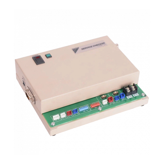
Page 7: Name Of Each Part
Name of each part RS-232C connector Power supply connector Power switch Serial Connector ... -
Page 8: Chapter 1 Installing Of Type 3 Software
: checker3_eng_v150.msi ( V150 is version ) 1.2 Installing of Checker TYPE 3 software When the Service Checker TYPE 3.1 is newly purchased, or the version-up of the TYPE 3 software (English) is made , install the new version of TYPE 3 software into the personal computer. - Page 9 2) Select installation folder 3) Installing software 4) Complete Chapter 1 Installing of TYPE 3 software - 8 -...
-
Page 10: Removing Checker Type 3 Software
Procedures 1) Use Installer module. Fallowing screen is displayed when the old version is already installed. Please select “Remove Daikin Service Checker Ver.1.xx”. 2) Using Control panel of Windows Click “Add or Remove Programs”, Select “checker TYPE3 software” and remove it. -
Page 11: Chapter 2 Connection To Air-Conditioner
Chapter 2 Connection to air-conditioner WARNING: 1. When using the Service Checker TYPE 3.1 in outdoor at rainy weather, be sure to protect it from rain so that it becomes free from the danger of electric shock and fires. - Page 12 Procedures 1) Screw tightly the clip-free end of DIII-NET connection cable made up by following the item (3) of the “Preparation” at DIII-NET terminals(F1, F2) of the Checker TYPE 3. (If an air-conditioner side is first connected and the resultant short-circuit should occur, it may cause the failures of the air-conditioner.) ...
-
Page 13: Sensor Connection
2.2 Sensor connection Features of sensor connection ・In case of air conditioners not conforming to the DIII-NET connection, it becomes possible to measure temperature and pressure by connecting the optional sensor kit (Parts Number: 999107T). ・Six temperature points and two pressure points are possible to measure. Among these points, two measurement points of temperature can be monitored as a signal of DC 0-5V or DC 0-1V via measuring instrument by shifting the switch. ... - Page 14 Using optional cable V (blue), connect to measuring instrument. To make V valid, place the upper switch in V side. V and Th6 are not possible to use V simultaneously. The conversion of a voltage signal from measuring instrument into voltage value is set by periodical recording in the “4.2 Setting of records”...
-
Page 15: Switching On The Power Supply Of Checker Type
2.3 Switching on the power supply of Checker TYPE 3 Procedures 1) Connect the RS-232C cable attached to the Checker TYPE 3.1 to the RS-232C connector of the Checker TYPE 3.1 and the Serial connector of a personal computer. ... -
Page 16: Chapter 3 Starting Up And Ending Of Type 3 Software
Chapter 3 Starting up and ending of TYPE 3 software 3.1 Starting up of TYPE 3 software Procedures 1) Start Service Checker software by start menu. 2) After the Service Checker software is started, the following main menu is displayed. [Record(F1)]... -
Page 17: Setting Of Customer Data
3.2 Setting of customer data The TYPE 3 software manages the operation data of every customer. For that reason, be sure to input customer ID at least. If the [Record only] without customer data management is used in the DIII-NET connection, since restart standby is applied every time at the side of an air conditioner, input customer data as much as possible. -
Page 18: Setting Of Ss Data
3.3 Setting of SS data Procedures 1) Press the [SS data(F5)] in the window of the [Main menu] to display the window of the [Input SS data]. 2) Input each item. Other than the item of [ In charge of ], use as memos. ・ ... -
Page 19: Ending Of Type 3 Software
3. 5 Ending of TYPE 3 software 1) When ending the TYPE 3 software, press the [End(F12)] button in the window of the [Main menu]. 2) In case of ending the TYPE 3 software after recording and playing back, it is necessary to repeat several times pressing the [Cancel(ESC)] to return to the window of the [Main menu]. -
Page 20: Chapter 4 Recording Of Operation Data
Chapter 4 Recording of operation data The TYPE 3 software manages data by the hierarchy structure of [customer-network map-operation data]. Customer Network map Operation data System 1: Mar. 23 System 2: Mar. 23 A building 1F System 1: Feb. 11 A customer :... - Page 21 ・ In case of recording operation data after inputting customer data for a new customer, press the [New customer(F3)] and display proceeds to the [Input customer data] window. Proceed to (3). ・ In case of recording operation data for a previously input customer, press the [Settlement customer(F2)] by placing the cursor in the customer name and display proceeds to the [Network map selection] window.
- Page 22 (4) This is the window of the [Network map selection]. (Notes) 1. For one customer, multiple network maps can be managed. 2. On the unit of network map, (1) In case of the DIII-NET connection, construct by every object, or even if the objects are same, construct separately each network map for both sides divided by DIII-NET expansion adapter(DTA109A1).
- Page 23 (5) This is the window of the [Access Method Selection]. (a) Be sure to input the [1. Network map name]. (b) Select the [2. Access method]. ・ [DIII-NET] : Possible to use only DIII-NET connection or in combination with Sensor input. Possible to use air conditioners conforming to the DIII-NET in internal and external transmission method.
-
Page 24: Displaying Of Network Map
4.1.2 Displaying of network map (Notes) If time setting of the personal computer is made after the window of the [Network Map Display], the order of data to be recorded is changed, resulting in not recording data correctly. Do not make time setting of the personal computer after the window of the [Network Map Display]. - Page 25 This is the window of the [Network Map Display]. (1) Reading of window. * The window displays outdoor units and indoor units in order of each auto-address by using icons. * The colors of the icons are changed depending on the state of an air conditioner.
- Page 26 (3) In the group of buttons displayed at the bottom of the window, by shifting a mode with the upper 3 buttons, the bottom 4 buttons can execute each function. A. Map mode(F3) Map mode(F3) Detail data input(F6) Centralized control(F7) Update map(F8) Print screen (F9) [Detail data input(F6)]:...
- Page 27 C. Recording mode(F5) Recording mode(F5) Periodical record Periodical record Trigger record Trigger inspection setting(F6) start(F7) setting(F8) start(F9) The method of recording operation data consists of two: one is the [Periodical recording] which records successively for a constant time, and another is the [Trigger recording] which records before and after meeting trigger conditions (conditions of digital data ON/OFF).
-
Page 28: Inputting Of Detailed Data
4.1.3 Inputting of detailed data The window of the [Detail data input] is displayed below. When pressing the button of the [Detail data input(F6)] after selecting the [Map mode(F3)] in the window of the [Network Map Display], the window of the [Detail data input] is displayed to enable to input the detail data of a system pointed with cursor (every outdoor unit). - Page 29 (4) By selecting another air conditioner with the [1.Airconditioner selection] to input necessary data, press the [Save(F1)]. (Notes) * In case of replacing PCB of an air conditioner, auto addresses in the network are changed. * If in the DIII-NET connection, a PCB of an air conditioner is replaced after making a network map once, the detail data for air conditioners will be deviated by reason of managing the detail data for each air conditioner in order of auto address.
-
Page 30: Selection Of Customer Data And Others
4.1.4 Displaying of operation data The window of the [Operation Data Display] is displayed below. The operation data for a system are displayed by pressing the button of the [Operation Data Display(F6)] after selecting the [Display mode(F4)] in the window of the [Network Map Display]. One window is displayed per one system. - Page 31 * Eight items per an air conditioner for analog data and digital data are displayed respectively. By placing the cursor in a data item to be displayed and pressing the [F12] key, the data item is marked at the left end by * and its graph is displayed in the left side of the window at the same time.
-
Page 32: Setting Of Recording
4.2 Setting of recording The method of recording operation data consists of two: one is the [Periodical recording] which records successively for a constant time, and another is the [Trigger recording] which records before and after meeting trigger conditions(conditions of digital data ON/OFF). - Page 33 The window of [Periodical record setting] Procedures 1) Set the [1.Recording interval], the [2. Recording end method], and the [3. Recording system selection]. Setting item Description 1) Select the time intervals recording in the hard disk of the personal computer.(5, 10, 20, 30, 60, 120, 180, 300, 600 seconds) 2) Since less time intervals need more recording data area for the hard disk, the initially set value of 20 seconds is recommended.
- Page 34 2) Set the [4. Setting of sensor input]. Select the [Recording] or [No recording], and also the [System] when recording. When recording, further press the [Sensor input setting(F2)]. Set the [Measurement data item] by following the window below. (Note) In case of shifting [Th5] to [A] or [Th6] to [V] by using the switch of the Checker TYPE 3, shift at a window before the window of [Display of network map], otherwise, operation data will not be recorded correctly.
- Page 35 3) Press the [Setting complete(F1)] in the window of the [Periodical recording Setting] to return to the [Network Map Display]. 4) When starting the [Periodical record], press the [Periodical record start(F7)] in the window of the [Network Map Display] to display the [Periodical recording] in red at the upper left in the window.
-
Page 36: Setting Of Periodical Recording (In Case Of Only Sensor Input Only)
4.2.2 Setting of periodical recording (in case of sensor input only) The window of the [Periodical record setting] is displayed by pressing the button of the [Periodical record setting(F6)] after selecting the [Recording mode(F5)] in the window of the [Network Map Display]. The window of the [Periodical record setting] Procedures... - Page 37 (5) When ending the periodical recording manually, press the [Periodical record end(F7)] If in the [Recording end method] of (1), the [Automatic] is set, recording data is ended automatically after pre-set [recording time] . - 36 - Chapter 4 Recording of operation data...
-
Page 38: Setting Of Trigger Recording
4.2.3 Setting of trigger recording * System 1 only is possible to set trigger recording in the TYPE 3 software. * The [Trigger recording] is a method which records before and after meeting trigger conditions (a combination of digital values (ON/OFF) of operation data). (Notes) 1. - Page 39 system By placing the cursor in the [System No.] to press the [F12] key, [Recording] selection or [No recording] is shifted. The left side of system recording trigger is marked *. The [Trigger conditions] can set two groups: the [Trigger condition 1] and the[Trigger condition 2].
-
Page 40: Centralized Operation
4.3 Centralized operation In the DIII-NET connection, the centralized operation of indoor units can be made from the Service Checker TYPE Ⅲ. (Notes) If no centralized control equipment on the DIII-NET is provided, set centralized address. After connecting the Checker TYPE 3 to the DIII-NET, and setting customer data by the TYPE 3 software, display the window of the [Network Map Display]. - Page 41 Procedures (1)Make centralized operation by placing the cursor at the icon of target air conditioner, and pressing the buttons at the bottom in the window and inputting figures. Button, Description Column Up(F1) Move upward in the window. Down(F2) Move downward in the window. Operation(F3) Command air conditioner to operate Stop(F4)
-
Page 42: Chapter 5 Playing Back Of Operation Data
Chapter 5 Playing back of operation data 5. 1 Playing of operation data Procedures (1) Press the [Play F2] in the [Main Menu] to display the window of the [Customer Data Selection]. (2) The window of the [Customer Data Selection] is displayed below. Place the cursor in the target operation data. - Page 43 [Delete(F9)]: The operation data are deleted. [Cancel(ESC)]: The return to the [Main Menu] is made. (3) The window of the [Operation data display] is shown below. * Refer to the “4.1.4 Displaying of operation data” regarding detailed display. When clicking the mouse on a graph, that data at the time are displayed in the right list .
- Page 44 [2] In case of error code Data with error code is searched. [Search from the top(F1)]: Searching is made from the top of operation data. [Search next(F2)]: Searching is made in the direction from a cursor position on a graph to time lapse. [Cancel(ESC)]: Returning to the window of the [Operation Data Display].
-
Page 45: Playing Back Of Network Map
5.2 Playing back network map The network map is played back from customer data. Procedures (1) Press the [Customer data(F4)] in the [Main Menu] to display the window of the [Customer Selection]. (2) The window of the [Customer Selection] is displayed below. Press the [Select customer(F2)] to display the window of the [Network Map Selection]. - Page 46 (4) The window of the [Network Map Display] is displayed below. [UP(F1)], [Down(F2)]: The window is scrolled upward and downward respectively. [Detail data input(F6)]: The detail data of an air conditioner designated by cursor are displayed. [Print screen(F9)]: Screen is printed. [Cancel(ESC)]: Return to the window of the [Network Map Selection].
-
Page 47: Csv Output
5.3 CSV output The data of CSV format possible to be read into by a commercial integrated software are output. Procedures 1) Press the [Play(F2)] in the [Main Menu] to display the window of the [Customer Data Selection]. 2) The window of the [Customer Data Selection] is displayed below. Press the [CSV data output(F3)] to display the window of the [Save with file name]. - Page 48 4) The window of the [Save with file name] is displayed below. Select the [Saving site] to input the [File name] and press the [Save] button. 5) While outputting CSV, the following window is displayed (Notes) 1. In the CSV file, one file per an air conditioner is output. In case of one outdoor unit and eight indoor units, one CSV file for the outdoor unit and eight CSV files for the eight indoor units are output respectively.
-
Page 49: Data Transfer
5.4 Data transfer To exchange customer data and operation data, data transfer to a floppy disk and other devices is possible. (Note) In case of exchanging data between personal computers, copy the data to a folder (directory) installed the TYPE 3 software in the section of the “1.1 Installing TYPE 3 software”. - Page 50 B. In case of transferring data from a floppy disk or other devices of a personal computer to the hard disk 1. Select the [Operation data] at the upper left in the window. 2. After setting the floppy disk or other devices to the personal computer, select the source of transfer by using the [Drive name] and the [Folder name](directory name) at the right side in the window.
-
Page 51: List Of Applicable Models
Specifications Specifications of Service Checker TYPE 3.1 Item Specifications External 180(width) x 150(depth) x 45(height)mm (excluding projecting sections) dimensions Weight Approx. 700g Power supply 5VDC, 300mA( USB B-type ) [ use PC, USB-adapter, USB-battery ]. Power consumption Approx. 1.2W Temperature and -10 to 55℃... - Page 52 Please follow Daikin’s purchasing procedure to purchase the checker and parts. Pentium is a registered trademark of Intel Corporation. Other product names mentioned above are trademarks or registered trademarks of respective companies. The above specifications are valid as of Nov, 2012 and they may be modified for improvement without any advance notice.
Need help?
Do you have a question about the Service Checker TYPE 3.1 and is the answer not in the manual?
Questions and answers