Advertisement
Quick Links
88 5022 307
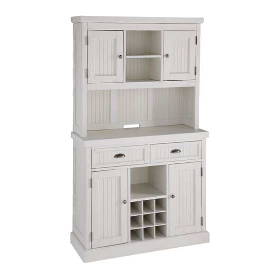
Nantucket
Hutch
IMPORTANT NOTE
Carefully remove all the parts from the carton and put
them individually on a soft cloth to prevent scratches
or other damages occuring to the wood parts.
We have taken great care in the design of this
product and request that you carefully and strictly
follow our assembly instructions to ensure a
completed product as it was designed.
Part List
A.
A.
Top
Top
1 pc.
1 pc.
G.
G.
Front Rail
ront Rail
1 pc.
pc.
I.
Shelf
2 pcs.
M.
Back Post
2 pcs.
Hardware List
Key Wrench
1 pc.
Small
Key Wrench
1 pc.
Tools required for assembly : Phillips screwdriver
B.
B.
Shelf
Shelf
1 pc.
H.
Shelf
1 pc.
J.
J.
Back Rail
Back Rail
1 pc.
1 pc.
N.
Back Panel
1 pc.
Cam Lock
16 pcs. (+1 extra)
Cam Lock Screw
16 pcs. (+1 extra)
C.
Side Panel
1 pc.
1 pc.
O.
O.
Back Rail
Back Rail
1 pc.
Wood Screw
20 pcs. (+2 extra)
Adjustable Pin
12 pcs. (+1 extra)
Tools recommended for assembly : Leve
E.
F.
Middle Panel
Middle Panel
1 pc.
1 pc.
D.
Side Panel
1 pc.
K.
Door
1 pc.
P.
Back Panel
3 pcs.
Pull Handle
2 pcs.
Machine Screw
Steel Plate
2 pcs.
Connector
2 pcs.
L.
Door
1 pc.
l
Advertisement

Related Manuals for Home Styles Nantucket Hutch


Summary of Contents for Home Styles Nantucket Hutch
- Page 1 88 5022 307 Nantucket Hutch IMPORTANT NOTE Carefully remove all the parts from the carton and put them individually on a soft cloth to prevent scratches or other damages occuring to the wood parts. We have taken great care in the design of this product and request that you carefully and strictly follow our assembly instructions to ensure a completed product as it was designed.
- Page 2 Assembly Instruction 2 / 4 IMPORTANT * Do not tighten up all the screws until each part is properly assembled. * You should keep Hex Wrench in a safe place as you may need to tighten up the Head Cap Bolts in the future. * Use a soft cloth between these parts and the fl...
- Page 3 Assembly Instruction 3 / 4 STEP 3 Attach Shelf (B) to unit using Cam Locks. Attach Middle Panels (E) and (F) to unit. Cam Lock Cam Lock STEP 4 Attach Front Rail (G) to unit using Cam Lock. Attach Side Panel (C) to unit with Cam Locks. Figure 3 Figure 4 Cam Lock...
- Page 4 Assembly Instruction 4 / 4 STEP 6 Insert 12X Wood Screws from the back of the unit. (see Figure 5) Note: Please make sure unit is level before tightening these screws. Wood Screw Wood Screw Figure 5 Steel Plate Connector Wood Screw Figure 6 Figure 6...
Need help?
Do you have a question about the Nantucket Hutch and is the answer not in the manual?
Questions and answers