Table of Contents
Advertisement
Quick Links
Advertisement
Table of Contents

Related Manuals for ADJ EVENT BAR PRO


Summary of Contents for ADJ EVENT BAR PRO
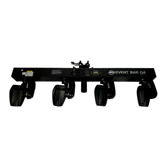
- Page 1 EVENT BAR PRO User Manual...
- Page 2 Products, LLC brands and product names are trademarks or registered trademarks of their respective companies. ADJ Products, LLC and all affiliated companies hereby disclaim any and all liabilities for property, equipment, building, and electrical damages, injuries to any persons, and direct or indirect economic...
-
Page 3: General Information
GENERAL INFORMATION Unpacking: Thank you for purchasing the Event Bar Pro by ADJ Products, LLC. Every Event Bar Pro has been thoroughly tested and has been shipped in perfect operating condition. Carefully check the shipping carton for damage that may have occurred during shipping. If the carton appears to have been damaged, carefully inspect your fixture for any damage and be sure all equipment necessary to operate the unit has arrived intact. -
Page 4: General Instructions
• Built-In Mount for a lighting stand (Stand Sold Separately) WARRANTY REGISTRATION The Event Bar Pro carries a 2 year (730 days) limited warranty. Please fill out the enclosed warranty card to validate your purchase and warranty. You may also register your product online at www.adj.com. All returned service items, whether under warranty or not, must be freight pre-paid and accompanied by a return authorization (R.A.) number. -
Page 5: Safety Precautions
SAFETY PRECAUTIONS For Your Own Personal Safety, Please Read and Understand This Manual Completely Before You Attempt To Install Or Operate This Unit! • To reduce the risk of electrical shock or fire, do not expose this unit to rain or moisture. •... -
Page 6: Dmx Set Up
DMX SET UP Power Supply: The ADJ Event Bar Pro contains an automatic voltage switch which will automatically sense the voltage when it is plugged into the power source. With this switch there is no need to worry about the correct power voltage, and this unit can be plugged in anywhere. - Page 7 XLR connector of the last unit in your daist chain to terminate the line. Using a cable terminator (ADJ part number Z-DMX/T) will decrease the possibilities of erratic behavior. 5-Pin XLR DMX Connectors. Some manufactures use 5-pin XLR connectors for DATA transmission in place of 3-pin.
-
Page 8: Installation
INSTALLATION The Event Bar Pro is fully operational in two different mounting positions: hanging upside-down from a ceiling or trussing, or attached to a sturdy tripod stand. The unit should be mounted using a mount- ing clamp (not provided), and affixing it to the mounting bracket that is provided with the unit. Always ensure that the unit is firmly fixed to avoid vibration and slipping while operating. -
Page 9: System Menu
SYSTEM MENU... - Page 10 SYSTEM MENU DMX Address - Set the DMX Address. 1. Press the MENU button until “DMX Addresss” is displayed, then press ENTER. 2. The currently selected address will now be displayed. Press the UP or DOWN buttons to scroll to your desired address.
- Page 11 SYSTEM MENU Sound State - In this mode the unit will run in sound active mode. 1. Press the MENU button until “Sound State” is displayed, then press ENTER. 2. Either “On” or “Off” will now be displayed, depending on the current setting. Use the UP or DOWN buttons to toggle between “On”...
- Page 12 SYSTEM MENU Fixture Time - With this function you can display the running time of the unit. 1. Press the MENU button until “Fixture Time” is displayed, then press ENTER. 2. The running time of the fixture will now be displayed. Press MENU to exit. Firmware Version - This will display the software version.
-
Page 13: Home Position Adjustment
HOME POSITION ADJUSTMENT With this function you can adjust and set the fixture’s home position. 1. Press the ENTER button for at least 3 seconds to enter into offset mode. 2. Press the UP or DOWN buttons until you find the setting that you would like to adjust. Selectable settings include Pan (Offset Px) and Tilt (Offset Tx) for moving heads 1 to 4. -
Page 14: Universal Dmx Control
Universal DMX Control: This function allows you to use a universal DMX-512 controller to create unique programs tailored to your individual needs. The Event Bar Pro has five different DMX channel modes. Refer to the System Menu section of •... -
Page 15: Channel Mode
2 CHANNEL MODE CHANNEL FUNCTION VALUES Shows 000 - 007 Blackout 008 - 037 Show 1 038 - 067 Show 2 068 - 097 Show 3 098 - 127 Show 4 128 - 157 Show 5 158 - 187 Show 6 188 - 217 Show 7 218 - 247 Show 8 248 - 254 Random Show... - Page 16 17 CHANNEL MODE CHANNEL FUNCTION VALUES 000 - 255 Pan (Head 1) 000 - 255 Pan Fine (Head 1) 000 - 255 Tilt (Head 1) 000 - 255 Tilt Fine (Head 1) 000 - 255 Pan (Head 2) 000 - 255 Pan Fine (Head 2) 000 - 255 Tilt (Head 2) 000 - 255 Tilt Fine (Head 2) 000 - 255 Pan (Head 3)
- Page 17 20 CHANNEL MODE CHANNEL FUNCTION VALUES 000 - 255 Pan (Head 1) 000 - 255 Pan Fine (Head 1) 000 - 255 Tilt (Head 1) 000 - 255 Tilt Fine (Head 1) 000 - 255 Head 1 Dimmer, 0% - 100% 000 - 255 Pan (Head 2) 000 - 255 Pan Fine (Head 2) 000 - 255 Tilt (Head 2)
- Page 18 22 CHANNEL MODE CHANNEL FUNCTION VALUES 000 - 255 Pan (Head 1) 000 - 255 Pan Fine (Head 1) 000 - 255 Tilt (Head 1) 000 - 255 Tilt Fine (Head 1) 000 - 255 Head 1 Dimmer, 0% - 100% 000 - 255 Pan (Head 2) 000 - 255 Pan Fine (Head 2) 000 - 255 Tilt (Head 2)
- Page 19 25 CHANNEL MODE CHANNEL FUNCTION VALUES 000 - 255 Pan (Head 1) 000 - 255 Pan Fine (Head 1) 000 - 255 Tilt (Head 1) 000 - 255 Tilt Fine (Head 1) 000 - 255 Head 1 Dimmer, 0% - 100% 000 - 255 Pan (Head 2) 000 - 255 Pan Fine (Head 2) 000 - 255 Tilt (Head 2)
- Page 20 25 CHANNEL MODE CHANNEL FUNCTION VALUES Shows 000 - 007 Blackout 008 - 037 Show 1 038 - 067 Show 2 068 - 097 Show 3 098 - 127 Show 4 128 - 157 Show 5 158 - 187 Show 6 188 - 217 Show 7 218 - 247 Show 8 248 - 254 Random Show...
-
Page 21: Photometric Chart
PHOTOMETRIC CHART DIMMER CURVE CHART POWER CORD DAISY CHAIN This feature allows you to connect the fixtures together via the IEC input and output sockets. The maximum number of fixtures that can be connected in this manner are as follows: • 5 fixtures maximum for 120V • 8 fixtures maximum for 240V After this value has been reached, a new power outlet is required in order to accommodate... -
Page 22: Fuse Replacement
FUSE REPLACEMENT Locate and disconnect the unit’s power cord, then find the fuse holder located inside the power socket. Remove the fuse holder by using a flat-head screwdriver to gently pry the fuse holder from its socket. Remove and discard the bad fuse from the fuse holder, and replace with a new fuse of the same rating. -
Page 23: Warranty
The sole responsibility of ADJ Products, LLC under this warranty shall be limited to the repair of the product, or replacement thereof, including parts, at the sole discretion of ADJ Products, LLC. -
Page 24: Specifications
ADJ Products, LLC 6122 S. Eastern Ave. Los Angeles, CA 90040 USA Tel: 323-582-2650 / Fax: 323-725-6100 Web: www.adj.com / E-mail: info@americandj.com A.D.J. Supply Europe B.V. Junostraat 2 6468 EW Kerkrade Netherlands service@adjgroup.eu / www.adj.eu...
Need help?
Do you have a question about the EVENT BAR PRO and is the answer not in the manual?
Questions and answers