Moxa Technologies AWK-3252A Series Quick Installation Manual
Hide thumbs
Also See for AWK-3252A Series:
- Quick installation manual (18 pages) ,
- User manual (161 pages)

Related Manuals for Moxa Technologies AWK-3252A Series


Summary of Contents for Moxa Technologies AWK-3252A Series
- Page 1 AWK-3252A Series Quick Installation Guide Moxa AirWorks Version 1.3, October 2022 Technical Support Contact Information www.moxa.com/support 2022 Moxa Inc. All rights reserved. P/N: 1802032520014 *1802032520014*...
-
Page 2: Hardware Setup
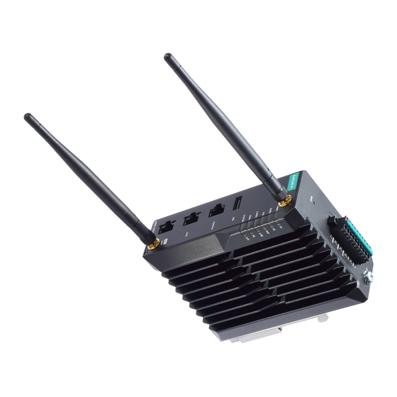
Overview The AWK-3252A Series is an industrial-grade AP/bridge/client with IEEE 802.11ac Wave 2 technology. This Series features concurrent dual-band Wi-Fi data transmissions up to 400 Mbps (2.4 GHz mode) and 867 Mbps (5 GHz mode) simultaneously, meeting the speed and flexibility requirements for industrial applications. - Page 3 Panel Layout of the AWK-3252A 1. Grounding screw (M5) 11. Screw holes for wall-mounting 2. Terminal blocks for PWR1, PWR2, relay, DI 1 and DI 2 12. DIN-rail mounting kit 3. Reset button 13. Cable holder screw 4. Antenna connector 2 5.
-
Page 4: Mounting Dimensions
Mounting Dimensions DIN-rail Mounting When shipped, the metal DIN-rail mounting kit is fixed to the back panel of the AWK-3252A. Mount the AWK-3252A on to a corrosion-free mounting rail that adheres to the EN 60715 standard. STEP 1: STEP 2: Insert the upper lip of the DIN-rail Press the AWK-3252A towards the kit into the mounting rail. - Page 5 To remove the AWK-3252A from the DIN rail, do the following: STEP 1: Pull down the latch on the DIN- rail kit with a screwdriver. STEP 2 & 3: Slightly pull the AWK-3252A forward and lift it up to remove it from the mounting rail.
-
Page 6: Wiring Requirements
STEP 3: Once the screws are fixed into the wall, insert the four screw heads through the large opening of the keyhole-shaped apertures, and then slide the AWK-3252A downwards (wall mounting) or forwards (ceiling mounting), as indicated to the right. Tighten the two screws for added stability. - Page 7 NOTE Do not run signal or communications wiring and power wiring in the same wire conduit. To avoid interference, wires with different signal characteristics should be routed separately. • You can use the type of signal transmitted through a wire to determine which wires should be kept separate.
- Page 8 Grounding the AWK-3252A Grounding and wire routing help limit the effects of noise due to electromagnetic interference (EMI). Run the ground connection from the ground screw to the grounding surface prior to connecting devices. ATTENTION This product is intended to be mounted to a well-grounded mounting surface, such as a metal panel.
-
Page 9: Terminal Block Pin Assignment
Terminal Block Pin Assignment The AWK-3252A comes with a 10-pin terminal block located on the top panel of the device. The terminal block contains dual power inputs, a relay output, and dual digital inputs. Refer to the following figure and table for the detailed pin assignment. -
Page 10: Wiring The Relay Contact
ATTENTION If the AWK-3252A is connected to a motor or other similar type of equipment, be sure to use power isolation protection. Before connecting the AWK-3252A to the DC power inputs, make sure the DC power source voltage is stable. Wiring the Relay Contact The AWK-3252A has one relay output, which consists of the two contacts of the terminal block on the AWK-3252A’s top panel. -
Page 11: Communication Connections
Communication Connections 10/100/1000BaseT(X) Ethernet Port Connection The 10/100/1000BaseT(X) ports located on the AWK-3252A’s front panel are used to connect to Ethernet-enabled devices. MDI/MDI-X Port Pinouts 1000BaseT 10/100BaseT 10/100BaseT MDI/MDI-X MDI-X TRD(0)+ TRD(0)– TRD(1)+ TRD(2)+ – – TRD(2)- – – TRD(1)- TRD(3)+ –... -
Page 12: Specifications
Color State Description Client/Client-Router/Slave has established a Wi-Fi connection to an AP/Master with a SNR value of 35 or higher. Green Data is being transmitted over the 2.4 GHz Blinking band. 2.4G Client/Client-Router/Slave has established a Wi-Fi connection to an AP/Master with a SNR value of less than 35. -
Page 13: Software Setup
ATTENTION The AWK-3252A is NOT a portable mobile device and should be located at least 50 cm away from the human body. The AWK-3252A is NOT designed for the general public. To ensure that your AWK-3252A wireless network is safe and configured correctly, consult a well-trained technician to assist with the installation process. - Page 14 Step 2: Connect the AWK to the notebook or PC via the • AWK’s LAN port. The LED indicator on the AWK’s LAN port will light up when a connection is established. NOTE If you are using an Ethernet-to-USB adapter, follow the instructions in the user’s manual provided with the adapter.
- Page 15 Step 5: Choose your country or region. • Select your country or region from the drop-down list and click NEXT. • Step 6: Create a user account and password. Enter the username, password, and email address for your user account and click CREATE. NOTE The username and password are case-sensitive.
-
Page 16: First-Time Quick Configuration
After creating your account, you will be automatically redirected to the login screen. Step 7: Log in to the device. • Enter your username and password and click LOG IN. The device will start initializing, this may take several seconds. Once the warning message has disappeared, you can log in using your username and password. - Page 17 AP/Client Mode Configuring the AWK as an AP Step 1: Set the operation mode of the AWK to AP mode. • Go to Wi-Fi Wireless Settings and select AP from the Operation Mode drop-down list. Step 2: Set up the AWK as an AP. •...
- Page 18 On the settings page, configure the SSID Status, SSID, RF Band, RTS/CTS Threshold, and Transmission Rate for the 5 GHz or 2.4 GHz band. When finished, click NEXT. On the second SSID Settings screen, configure the SSID Broadcast Status and Security type. From here, you can also copy the configuration over to the second SSID.
- Page 19 Configuring the AWK as a Client Step 1: Set the operation mode of the AWK to Client mode. • Go to Wi-Fi Wireless Settings and select Client from the Operation Mode drop-down list, set the SSID, and click Apply. For more detailed configurations, refer to the AWK-3252A User’s Manual.
- Page 20 Configuring the AWK as a Master Step 1: Set the operation mode of the AWK to Master mode. • Go to Wi-Fi Wireless Settings and select Master from the Operation Mode drop-down list. • Step 2: Set up the AWK as a Master. Click the ADD icon to create a new SSID.
- Page 21 On the settings page, configure the SSID Status, Master/AP (select Master),SSID, RF Band, RTS/CTS Threshold, and Transmission Rate for the 5 GHz or 2.4 GHz band. When finished, click NEXT. On the second SSID Settings screen, configure the SSID Broadcast Status and Security type. From here, you can also copy the configuration over to the second SSID.
-
Page 22: Fcc/Ic Statements
Configuring the AWK as a Slave Step 1: Set the operation mode of the AWK to Slave mode. • Go to Wi-Fi Wireless Settings and select Slave from the Operation Mode drop-down list, set the SSID, and click Apply. For more detailed configurations, refer to the AWK-3252A User’s Manual. - Page 23 Radio Transmitters (Part 15) This device complies with part 15 of the FCC Rules. Operation is subject to the following two conditions: 1. This device may not cause harmful interference. 2. This device must accept any interference received, including interference that may cause undesired operation. IMPORTANT NOTE This device is restricted to mobile configuration.
- Page 24 Cet appareil a également été évalué et montré conforme aux limites d'exposition RF ISED dans des conditions d'exposition mobiles. (Les antennes sont à plus de 50 cm du corps d'une personne). NCC Statements 經型式認證合格之低功率射頻電機,非經許可,公司、商號或使用者均不得擅自變 更頻率、加大功率或變更原設計之特性及功能。 低功率射頻電機之使用不得影響飛航安全及干擾合法通信;經發現有干擾現象時, 應立即停用,並改善至無干擾時方得繼續使用。 前項合法通信,指依電信法規定作業之無線電通信。低功率射頻電機須忍受合法通 信或工業、科學及醫療用電波輻射性電機設備之干擾。 應避免影響附近雷達系統之操作。 KC Statements 이...
-
Page 25: Warning - Explosion Hazard
Address of the No. 1111, Heping Rd., Bade Dist., Taoyuan City manufacturer 334004, Taiwan • The devices shall be installed in an enclosure that provides a degree of protection not less than IP54 Safe Use in accordance with IEC/EN 60079-0 and accessible Conditions only by the use of a tool.
Need help?
Do you have a question about the AWK-3252A Series and is the answer not in the manual?
Questions and answers