Table of Contents
Advertisement
Quick Links
www.ti.com
User's Guide
DRV8316REVM Evaluation Module
This document is provided with the
DRV8316x data sheet (DRV8316 4.5-V to 35-V Three-Phase Smart Gate
hardware implementation of the EVM and how to setup and power the board.
Warnings..........................................................................................................................................................2
2
Introduction.............................................................................................................................................................................3
Guide....................................................................................................................................................................4
4.1 Hardware Connections Overview - DRV8316REVM + LAUNCHXL-F280049C...............................................................
4.2 Connection Details.............................................................................................................................................................
4.3 LEDs, Switches, and Jumpers...........................................................................................................................................
5 Hardware Setup....................................................................................................................................................................
Application.............................................................................................................................................15
™
™
Identification...........................................................................................................................................................16
6.3 Sensorless Sinusoidal Commutation ..............................................................................................................................
6.4 Torque and Speed Control...............................................................................................................................................
6.5 DRV8316 SPI Communication.........................................................................................................................................
7 DRV8316REVM Schematics.................................................................................................................................................
8 Revision History...................................................................................................................................................................
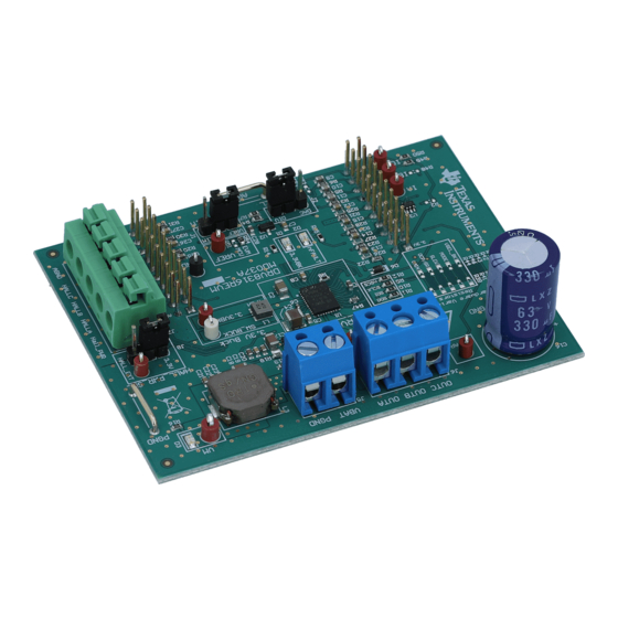
Figure 2-1. DRV8316REVM PCB Layout....................................................................................................................................
Figure 4-1. Major DRV8316REVM Hardware Blocks..................................................................................................................
Figure 4-2. Connections From Motor to DRV8316REVM............................................................................................................
Figure 4-5. User-Selectable Jumpers and DNP Components on Top Side of DRV8316REVM................................................
Figure 4-7. Resistor Divider Settings (R37-R46) and Resistors to Disable SPI (R9-R12).........................................................
™
™
Figure 6-3. Motor Identification Using the DRV8316REVM InstaSPIN
Figure 7-1. Main Supply, Reverse Polarity Protection, and Pi Filter Schematic........................................................................
Figure 7-2. Voltage Sense and Protection Schematic...............................................................................................................
Figure 7-3. Connectors and Interface Schematic......................................................................................................................
Figure 7-5. VREF / ILIM Schematic...........................................................................................................................................
Figure 7-6. 3.3V Integrated Buck Regulator Schematic............................................................................................................
Figure 7-7. TMS430F280049C LaunchPad Connections Schematic........................................................................................
Schematic...........................................................................................................................................22
SLVUBZ9A - DECEMBER 2020 - REVISED FEBRUARY 2021
Submit Document Feedback
DRV8316R customer evaluation module (EVM)
Table of Contents
Overview.........................................................................................................................................5
GUI.................................................................................................................................15
List of Figures
LEDs...............................................................................................................................................8
™
DRV8316REVM........................................................................................15
™
Universal GUI Downloading Program...................................................................................
Schematic..................................................................................................20
Copyright © 2021 Texas Instruments Incorporated
ABSTRACT
Driver). This user's guide details the
™
.........................................................................
™
and Micro-USB Plugged Into LaunchPad
DRV8316REVM...............................................10
MCU.............................................................14
™
GUI............................................................................16
™
GUI................................................................
™
GUI..........................................................................
Table of Contents
as a supplement to the
™
GUI................................................
DRV8316REVM Evaluation Module
5
5
8
12
14
17
17
18
19
22
3
5
6
™
...........
7
10
11
16
17
17
18
19
19
20
21
21
21
1
Advertisement
Table of Contents

Related Manuals for Texas Instruments DRV8316REVM


Summary of Contents for Texas Instruments DRV8316REVM
-
Page 1: Table Of Contents
... Figure 4-4. DRV8316REVM LEDs...............................8 Figure 4-5. User-Selectable Jumpers and DNP Components on Top Side of DRV8316REVM..........Figure 4-6. User-Selectable Jumpers and DNP Components on Bottom Side DRV8316REVM..........10 Figure 4-7. Resistor Divider Settings (R37-R46) and Resistors to Disable SPI (R9-R12)............ -
Page 2: Cautions And Warnings
List of Tables Table 4-1. Description of DRV8316REVM LEDs (default Upon powerup in bold)............... Table 4-2. Description of User Selectable Settings on DRV8316REVM (default in bold)............Table 4-3. Status of Resistors for DRV8316R and DRV8316T Variants (defaults in bold)............11 Table 4-4. -
Page 3: Introduction
LaunchPad ™ MCU and DRV8316R. For step-by-step details on connecting the LAUNCHXL-F280049C + DRV8316REVM, installing software, and running the project to spin a motor, refer to Section 5 Hardware Setup. Figure 2-1. DRV8316REVM PCB Layout SLVUBZ9A –... -
Page 4: Quick Start Guide
3 Quick Start Guide The DRV8316REVM requires a power-supply source, which has a recommended operating range from 4.5 V to 35 V. To setup and power the EVM, use the following sequence: 1. Connect the power supply ground to PGND of the two-pin power connector J5 and the voltage pin to the VBAT pin. -
Page 5: Hardware And Software Overview
The three phases of the BLDC motor connect directly to the OUTA, OUTB, and OUTC terminals of the screw terminal provided on the DRV8316REVM. To connect Hall sensor outputs to the Hall connector on the DRV8316REVM, push down on the respective terminals to open the sockets and insert the Hall sensor connections. -
Page 6: Figure 4-2. Connections From Motor To Drv8316Revm
Micro-USB cable is plugged into the LAUNCHXL-F280049C to provide communication between the LaunchPad firmware and GUI as well as the correct installment of the DRV8316REVM to the J1/J3 and J2/J4 headers of the LaunchPad. DRV8316REVM Evaluation Module SLVUBZ9A –... -
Page 7: Figure 4-3. Drv8316Revm On Headers J1/J3 And J2/J4 Of Launchpad
Hardware and Software Overview Figure 4-3. DRV8316REVM on Headers J1/J3 and J2/J4 of LaunchPad ™ and Micro-USB Plugged Into LaunchPad ™ SLVUBZ9A – DECEMBER 2020 – REVISED FEBRUARY 2021 DRV8316REVM Evaluation Module Submit Document Feedback Copyright © 2021 Texas Instruments Incorporated... -
Page 8: Leds, Switches, And Jumpers
The DRV8316REVM has four status LEDs implemented on the board. By default, the VM and 3.3VBK LEDs will light up when the board is powered and the MCU LED (tied to GPIO59) can be used for debugging and validation. - Page 9 Hardware and Software Overview The DRV8316REVM includes a variety of user-selectable jumpers and unpopulated components on the bottom and top layers of the PCB to choose user settings and evaluate the DRV8316R/T device. A summary of those selectable settings are listed in...
-
Page 10: Figure 4-5. User-Selectable Jumpers And Dnp Components On Top Side Of Drv8316Revm
Hardware and Software Overview www.ti.com Figure 4-5. User-Selectable Jumpers and DNP Components on Top Side of DRV8316REVM Figure 4-6. User-Selectable Jumpers and DNP Components on Bottom Side DRV8316REVM DRV8316REVM Evaluation Module SLVUBZ9A – DECEMBER 2020 – REVISED FEBRUARY 2021 Submit Document Feedback... -
Page 11: Figure 4-7. Resistor Divider Settings (R37-R46) And Resistors To Disable Spi (R9-R12)
Hardware and Software Overview 4.3.1 DRV8316T Compatibility The DRV8316REVM is compatible with the DRV8316T (H/W variant) as the featured motor driver IC to spin a three-phase Brushless-DC motor. The DRV8316T replaces the SPI settings with five specific pin settings (MODE, SLEW, OCP/SR, GAIN, and VSEL_BK) that can be adjusted through resistor dividers. -
Page 12: Interfacing Drv8316Revm And Launchxl-F280049C Launchpad
4.4 Interfacing DRV8316REVM and LAUNCHXL-F280049C LaunchPad ™ The DRV8316REVM has 40 pins with different functions. These pins are interfaced with the LAUNCHXL- F280049C LaunchPad development kit and are mapped appropriately to receive the functionalities of the DRV8316R device. These 40 pins are grouped into 4 ports in respect to the LAUNCHXL-F280049C (J1 to J4). - Page 13 Hardware and Software Overview Table 4-5. Connections for Header J3 on DRV8316REVM (DNP in bold) (continued) J3 Pin DRV8316REVM LAUNCHXL-F280049C Description Number Function Function nFAULT (DNP) ADCINC4 For internal use only ISENB ADCINC0 Phase B current sense nSLEEP GPIO37...
-
Page 14: Hardware Setup
5 Hardware Setup The hardware required to run the motor control is the LAUNCHXL-F280049C LaunchPad development kit, the DRV8316REVM, a Micro-USB cable, and a power supply with a DC output from 8-V to 32-V. Follow these steps to start up the DRV8316REVM: 1. -
Page 15: Firmware And Gui Application
Firmware and GUI Application 6 Firmware and GUI Application The DRV8316REVM can implement sensored, sensorless, or Field-oriented control for commutating a three- phase Brushless-DC motor. The supported firmware is a sensorless ield-oriented control algorithm adapted from Texas Instruments’ MotorControl SDK Library of motor solutions. The algorithm includes motor identification and parameters, sensorless sinusoidal commutation, torque and speed control, and field weakening to maximize the performance of the motor. -
Page 16: Motor Identification
Figure 6-3. These values will be automatically used for Field-oriented control modulation techniques such as MTPA, Field-weakening, and PowerWarp (EPL). Figure 6-3. Motor Identification Using the DRV8316REVM InstaSPIN ™ DRV8316REVM Evaluation Module SLVUBZ9A – DECEMBER 2020 – REVISED FEBRUARY 2021 Submit Document Feedback Copyright ©... -
Page 17: Sensorless Sinusoidal Commutation
“user.h” of the InstaSPIN firmware. Figure 6-5. Torque and Speed Control Using the DRV8316REVM InstaSPIN ™ SLVUBZ9A – DECEMBER 2020 – REVISED FEBRUARY 2021... -
Page 18: Drv8316 Spi Communication
To read data from a specific address, input the address in decimal into the address above the “Manual Read” box. Click on the “Manual Write” box to read the data from that address. Figure 6-6. SPI Communication Using the DRV8316REVM InstaSPIN ™... -
Page 19: Drv8316Revm Schematics
7 DRV8316REVM Schematics Figure 7-1. Main Supply, Reverse Polarity Protection, and Pi Filter Schematic Figure 7-2. Voltage Sense and Protection Schematic SLVUBZ9A – DECEMBER 2020 – REVISED FEBRUARY 2021 DRV8316REVM Evaluation Module Submit Document Feedback Copyright © 2021 Texas Instruments Incorporated... -
Page 20: Figure 7-3. Connectors And Interface Schematic
DRV8316REVM Schematics www.ti.com Figure 7-3. Connectors and Interface Schematic Figure 7-4. DRV8316 3-phase BLDC Motor Driver Schematic DRV8316REVM Evaluation Module SLVUBZ9A – DECEMBER 2020 – REVISED FEBRUARY 2021 Submit Document Feedback Copyright © 2021 Texas Instruments Incorporated... -
Page 21: Figure 7-5. Vref / Ilim Schematic
DRV8316REVM Schematics Figure 7-5. VREF / ILIM Schematic Figure 7-6. 3.3V Integrated Buck Regulator Schematic Figure 7-7. TMS430F280049C LaunchPad Connections Schematic SLVUBZ9A – DECEMBER 2020 – REVISED FEBRUARY 2021 DRV8316REVM Evaluation Module Submit Document Feedback Copyright © 2021 Texas Instruments Incorporated... -
Page 22: Revision History
Changes from Revision * (December 2020) to Revision A (February 2021) Page • Added Cautions and Warnings section.......................2 • Changed instructions in the C2000™ InstaSPIN™ Universal GUI section............DRV8316REVM Evaluation Module SLVUBZ9A – DECEMBER 2020 – REVISED FEBRUARY 2021 Submit Document Feedback Copyright © 2021 Texas Instruments Incorporated... - Page 23 TI products. TI’s provision of these resources does not expand or otherwise alter TI’s applicable warranties or warranty disclaimers for TI products.IMPORTANT NOTICE Mailing Address: Texas Instruments, Post Office Box 655303, Dallas, Texas 75265 Copyright © 2021, Texas Instruments Incorporated...
Need help?
Do you have a question about the DRV8316REVM and is the answer not in the manual?
Questions and answers