Sign In
Upload
Manuals
Brands
Texas Instruments Manuals
Motherboard
DRV8316 EVM Series
Texas Instruments DRV8316 EVM Series Manuals
Manuals and User Guides for Texas Instruments DRV8316 EVM Series. We have
2
Texas Instruments DRV8316 EVM Series manuals available for free PDF download: User Manual
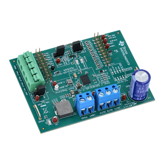
Texas Instruments DRV8316 EVM Series User Manual (28 pages)
Evaluation Module
Brand:
Texas Instruments
| Category:
Motherboard
| Size: 2.48 MB
Table of Contents
Table of Contents
1
1 Cautions and Warnings
3
2 Introduction
4
Figure 2-1. Drv8316Xevm PCB Layout
4
Table 2-1. DRV8316
4
3 Quick Start Guide
5
4 Hardware and Software Overview
6
Leds, Switches, and Jumpers
6
Table 4-1. Description of Drv8316Xevm Leds (Default Upon Powerup in Bold)
6
Figure 4-1. Drv8316Xevm Leds
7
Table 4-2. Description of User Selectable Settings on Drv8316Xevm
8
Figure 4-2. User-Selectable Jumpers and DNP Components on Top Side of Drv8316Xevm
9
Figure 4-3. User-Selectable Jumpers and DNP Components on Bottom Side Drv8316Xevm
10
Table 4-3. Status of Resistors for DRV8316R and DRV8316T Variants (Defaults in Bold)
10
Figure 4-4. Resistor Divider Settings (R37-R46) and Resistors to Disable SPI (R9-R12)
11
Table 4-4. User-Adjustable Resistor Divider Settings for DRV8316T Variant
11
Hardware Connections Overview - Drv8316Xevm + LAUNCHXL-F280049C
12
Connection Details
13
Figure 4-5. Major Drv8316Xevm Hardware Blocks
13
Figure 4-6. Connections from Motor to Drv8316Xevm
14
Figure 4-7. Drv8316Xevm on Headers J1/J3 and J2/J4 of Launchpad
15
Interfacing Drv8316Xevm and LAUNCHXL-F280049C Launchpad
16
5 Hardware Setup
18
Figure 5-1. Bottom Silk Screen Shows Names of Pins When Using an External MCU
18
6 Firmware and GUI Application
19
C2000 Instaspin Universal GUI
19
Figure 6-1. C2000 ™ Instaspin ™ Universal GUI for Drv8316Xevm
19
Motor Identification
20
Figure 6-2. C2000 ™ Instaspin ™ Universal GUI Downloading Program
20
Figure 6-3. Motor Identification Using the Drv8316Xevm Instaspin ™ GUI
21
Sensorless-FOC Commutation
22
Torque and Speed Control
22
Figure 6-4. Sensorless Sinusoidal Commutation Using the Drv8316Xevm Instaspin ™ GUI
22
SPI Communication (DRV8316R Only)
23
Figure 6-5. SPI Communication Using the Drv8316Xevm Instaspin ™ GUI
23
7 Drv8316Xevm Schematics
24
Figure 7-1. Main Supply, Reverse Polarity Protection, and Pi Filter Schematic
24
Figure 7-2. Voltage Sense and Protection Schematic
24
Figure 7-3. Connectors and Interface Schematic
25
Figure 7-4. DRV8316 3-Phase BLDC Motor Driver
25
Figure 7-5. VREF / ILIM Schematic
26
Figure 7-6. 3.3V Integrated Buck Regulator Schematic
26
Figure 7-7. TMS430F280049C Launchpad Connections Schematic
26
8 Revision History
27
Figure 7-8. Status Leds
27
Advertisement
Texas Instruments DRV8316 EVM Series User Manual (23 pages)
Brand:
Texas Instruments
| Category:
Motherboard
| Size: 14.42 MB
Table of Contents
Table of Contents
1
1 Cautions and Warnings
2
2 Introduction
3
Figure 2-1. DRV8316REVM PCB Layout
3
3 Quick Start Guide
4
4 Hardware and Software Overview
5
Hardware Connections Overview - DRV8316REVM + LAUNCHXL-F280049C
5
Connection Details
5
Figure 4-1. Major DRV8316REVM Hardware Blocks
5
Figure 4-2. Connections from Motor to DRV8316REVM
6
Figure 4-3. DRV8316REVM on Headers J1/J3 and J2/J4 of Launchpad
7
Leds, Switches, and Jumpers
8
Figure 4-4. DRV8316REVM Leds
8
Figure 4-5. User-Selectable Jumpers and DNP Components on Top Side of DRV8316REVM
10
Figure 4-6. User-Selectable Jumpers and DNP Components on Bottom Side
10
Drv8316Revm
10
Figure 4-7. Resistor Divider Settings (R37-R46) and Resistors to Disable SPI (R9-R12)
11
Interfacing DRV8316REVM and LAUNCHXL-F280049C Launchpad
12
5 Hardware Setup
14
Figure 5-1. Bottom Silk Screen Shows Names of Pins When Using an External MCU
14
6 Firmware and GUI Application
15
C2000 Instaspin Universal GUI
15
Figure 6-1. C2000 ™ Instaspin ™ Universal GUI for DRV8316REVM
15
Motor Identification
16
Figure 6-2. C2000 ™ Instaspin ™ Universal GUI Downloading Program
16
Gui
16
Sensorless Sinusoidal Commutation
17
Torque and Speed Control
17
Figure 6-4. Sensorless Sinusoidal Commutation Using the DRV8316REVM Instaspin ™ GUI
17
Figure 6-5. Torque and Speed Control Using the DRV8316REVM Instaspin ™ GUI
17
DRV8316 SPI Communication
18
Figure 6-6. SPI Communication Using the DRV8316REVM Instaspin ™ GUI
18
7 DRV8316REVM Schematics
19
Figure 7-1. Main Supply, Reverse Polarity Protection, and Pi Filter Schematic
19
Figure 7-2. Voltage Sense and Protection Schematic
19
Figure 7-3. Connectors and Interface Schematic
20
Figure 7-4. DRV8316 3-Phase BLDC Motor Driver
20
Figure 7-5. VREF / ILIM Schematic
21
Figure 7-6. 3.3V Integrated Buck Regulator Schematic
21
Figure 7-7. TMS430F280049C Launchpad Connections Schematic
21
8 Revision History
22
Figure 7-8. Status Leds Schematic
22
Advertisement
Related Products
Texas Instruments DRV8316R
Texas Instruments DRV8316T
Texas Instruments DRV8316REVM
Texas Instruments DRV8317HEVM
Texas Instruments DRV8300-EVM Series
Texas Instruments DRV8300DIPW-EVM
Texas Instruments DRV8303EVM
Texas Instruments DRV8329AEVM
Texas Instruments DRV8329
Texas Instruments DRV8328 EVM Series
Texas Instruments Categories
Motherboard
Control Unit
Microcontrollers
Computer Hardware
Calculator
More Texas Instruments Manuals
Login
Sign In
OR
Sign in with Facebook
Sign in with Google
Upload manual
Upload from disk
Upload from URL