Table of Contents
Advertisement
Quick Links
www.ti.com
User's Guide
DRV8328xEVM User's Guide
This document is provided with the
DRV8328x data sheet (DRV8328 4.5-V to 60-V Three-Phase Smart Gate
implementation of the EVM and shows how to set up and power the board.
The DRV8328AEVM comes automatically populated with and configured for the DRV8328A. It is also
compatible for the DRV8328B, DRV8328C, and DRV8328D variants (see
3.4.2), but the user will need to modify the board to make it compatible for each variant (see
and
Table
3-4).
1
Introduction.............................................................................................................................................................................2
Guide....................................................................................................................................................................4
3.2 Connection Details.............................................................................................................................................................
Lights..........................................................................................................................................................................7
3.5 Interfacing DRV8328AEVM and LAUNCHXL-F280049C LaunchPad.............................................................................
4 Hardware Setup....................................................................................................................................................................
Application.............................................................................................................................................17
DRV8328AEVM-GUI...........................................................................................................................17
DRV8328AEVM-GUI........................................................................................................................................19
6
Schematics............................................................................................................................................................................20
6.1
DRV8328A/B/C/D.............................................................................................................................................................20
6.2 DRV8328C/D variant select.............................................................................................................................................
6.3 Status LEDs.....................................................................................................................................................................
6.5 External 3.3V LDO...........................................................................................................................................................
6.6 Power Stage and MOSFETs............................................................................................................................................
6.7 Main Supply Input............................................................................................................................................................
6.8 Hall Sensor and Hall Power Selection.............................................................................................................................
6.9 Connectors, Selectors, and Analog Control Interface......................................................................................................
Protection........................................................................................................................................27
7 Revision History...................................................................................................................................................................
SLVUCD3 - NOVEMBER 2021
Submit Document Feedback
DRV8328 customer evaluation module (EVM)
Table of Contents
Overview.........................................................................................................................................5
Functions.......................................................................................................9
Guide...........................................................................................................................18
Connections........................................................................................................................22
Copyright © 2021 Texas Instruments Incorporated
ABSTRACT
Driver). This User's Guide details the
Note
LAUNCHXL-F280049C................................................................5
Table of Contents
as a supplement to the
Section 3.4.1
and
Section
Table 3-3
DRV8328xEVM User's Guide
5
14
16
21
21
23
23
24
25
26
28
1
Advertisement
Table of Contents

Related Manuals for Texas Instruments DRV8328 EVM Series


Summary of Contents for Texas Instruments DRV8328 EVM Series
-
Page 1: Table Of Contents
6.7 Main Supply Input................................6.8 Hall Sensor and Hall Power Selection..........................6.9 Connectors, Selectors, and Analog Control Interface...................... 6.10 Voltage Sense and Protection............................27 7 Revision History................................... SLVUCD3 – NOVEMBER 2021 DRV8328xEVM User's Guide Submit Document Feedback Copyright © 2021 Texas Instruments Incorporated... -
Page 2: Introduction
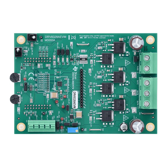
It also is intended to help engineers design, implement, and validate reference hardware and software for the LaunchPad MCU and DRV8328. For step by step details on connecting the LAUNCHXL- F280049C + DRV8328AEVM, refer to Section DRV8328xEVM User's Guide SLVUCD3 – NOVEMBER 2021 Submit Document Feedback Copyright © 2021 Texas Instruments Incorporated... - Page 3 Introduction Figure 1-1. DRV8328AEVM PCB Layout SLVUCD3 – NOVEMBER 2021 DRV8328xEVM User's Guide Submit Document Feedback Copyright © 2021 Texas Instruments Incorporated...
-
Page 4: Quick Start Guide
6. Connect a Micro-USB cable from the computer into the Micro USB connector on the top of the LAUNCHXL- F280049C as shown in Figure 3-3. DRV8328xEVM User's Guide SLVUCD3 – NOVEMBER 2021 Submit Document Feedback Copyright © 2021 Texas Instruments Incorporated... -
Page 5: Hardware And Software Overview
For sensored applications, to connect the Hall sensor outputs to the Hall connectors on the DRV8328AEVM, push down on the respective terminals to open the sockets and insert the Hall sensor wires into connector J10. SLVUCD3 – NOVEMBER 2021 DRV8328xEVM User's Guide Submit Document Feedback Copyright © 2021 Texas Instruments Incorporated... - Page 6 LaunchPad firmware and GUI as well as the correct installment of the DRV8328AEVM to the J1/J3 and J2/J4 headers of the LaunchPad. DRV8328xEVM User's Guide SLVUCD3 – NOVEMBER 2021 Submit Document Feedback Copyright © 2021 Texas Instruments Incorporated...
-
Page 7: Led Lights
There are LED indicators on both the LAUNCHXL-F280049C and DRV8328AEVM when power is provided and the micro USB cable is plugged in to the LaunchPad. SLVUCD3 – NOVEMBER 2021 DRV8328xEVM User's Guide Submit Document Feedback Copyright © 2021 Texas Instruments Incorporated... - Page 8 Green Power is supplied to the board MCU_LED Orange MCU debugging nFAULT 3.3V LDO (A/B) or AVDD (C/D) LED PVDD Figure 3-5. DRV8328AEVM LEDs DRV8328xEVM User's Guide SLVUCD3 – NOVEMBER 2021 Submit Document Feedback Copyright © 2021 Texas Instruments Incorporated...
-
Page 9: Drv8328Aevm Configurability And Switch Functions
J11 = AVDD Supplies AVDD to Hall power from 3.3 V or 5 V. power J11 = EXT Supply external hall power from HALL_PWR_EXT SLVUCD3 – NOVEMBER 2021 DRV8328xEVM User's Guide Submit Document Feedback Copyright © 2021 Texas Instruments Incorporated... - Page 10 Phase A voltage feedback filtering capacitor for R68, R71, C46 Phase B voltage feedback phase voltage feedback to R69, R72, C47 Phase C voltage feedback MCU ADCs. DRV8328xEVM User's Guide SLVUCD3 – NOVEMBER 2021 Submit Document Feedback Copyright © 2021 Texas Instruments Incorporated...
- Page 11 A/B variant when the DRV8328A or DRV8328B is used. Ensure resistors R1-R10 are removed, C1 is removed, and resistors R11-R21 are populated (except R16). SLVUCD3 – NOVEMBER 2021 DRV8328xEVM User's Guide Submit Document Feedback Copyright © 2021 Texas Instruments Incorporated...
- Page 12 Brushless-DC motor but requires modifications to the EVM. The main modifications are removing and populating the correct 0-ohm resistors so pins of the DRV8328C/D variants are properly configured for their functions. DRV8328xEVM User's Guide SLVUCD3 – NOVEMBER 2021 Submit Document Feedback Copyright © 2021 Texas Instruments Incorporated...
- Page 13 Table 3-4. DRV8328C/D pinout, functions, and populated resistors DRV8328C/D Pin Function Populated Components DRVOFF AVDD R4/C1 INHC INHB INHA INLC INLB INLA nSLEEP nFAULT SLVUCD3 – NOVEMBER 2021 DRV8328xEVM User's Guide Submit Document Feedback Copyright © 2021 Texas Instruments Incorporated...
-
Page 14: Interfacing Drv8328Aevm And Launchxl-F280049C Launchpad
PWM used to switch Phase B High-side FET nFAULT_DFLT nFAULT for internal use only. INLB GPIO9/PWM5B PWM used to switch Phase B Low-side FET Not used Not used DRV8328xEVM User's Guide SLVUCD3 – NOVEMBER 2021 Submit Document Feedback Copyright © 2021 Texas Instruments Incorporated... - Page 15 If multiple signal paths are present, or no signal path is present, the device may not work as intended. SLVUCD3 – NOVEMBER 2021 DRV8328xEVM User's Guide Submit Document Feedback Copyright © 2021 Texas Instruments Incorporated...
-
Page 16: Hardware Setup
If using the DRV8328AEVM with an external microcontroller, make the connections needed on the male headers on the top of the board or female connectors on the bottom side of the board. DRV8328xEVM User's Guide SLVUCD3 – NOVEMBER 2021 Submit Document Feedback Copyright © 2021 Texas Instruments Incorporated... -
Page 17: Firmware And Gui Application
Accept the readme that appears. The GUI will detect the LAUNCHXL-F280049C and automatically download the program into the MCU. Once complete, the “Hardware Connected” message appears at the bottom left hand corner as shown in Figure 5-2. SLVUCD3 – NOVEMBER 2021 DRV8328xEVM User's Guide Submit Document Feedback Copyright © 2021 Texas Instruments Incorporated... -
Page 18: Drv8328Aevm-Gui Quick Start Guide
2. Adjust the MCU dead time and Acceleration Delay values. For DRV8328A/B, it is recommended to use the DT potentiometer and set MCU dead time to 0 ns. DRV8328xEVM User's Guide SLVUCD3 – NOVEMBER 2021 Submit Document Feedback Copyright © 2021 Texas Instruments Incorporated... -
Page 19: Using The Drv8328Aevm-Gui
PVDD Undervoltage Fault – PVDD is under 4.5 V. Over-Current – Measured LSS current is over the Over-Current threshold. DRV8328 Fault – Fault indicated by the DRV8328. See DRV8328 datasheet. SLVUCD3 – NOVEMBER 2021 DRV8328xEVM User's Guide Submit Document Feedback Copyright © 2021 Texas Instruments Incorporated... -
Page 20: Schematics
Schematics www.ti.com 6 Schematics 6.1 DRV8328A/B/C/D Figure 6-1. DRV8328A/B/C/D Schematic DRV8328xEVM User's Guide SLVUCD3 – NOVEMBER 2021 Submit Document Feedback Copyright © 2021 Texas Instruments Incorporated... -
Page 21: Drv8328C/D Variant Select
Schematics 6.2 DRV8328C/D variant select Figure 6-2. DRV8328C/D variant select schematic 6.3 Status LEDs Figure 6-3. Status LEDs schematic SLVUCD3 – NOVEMBER 2021 DRV8328xEVM User's Guide Submit Document Feedback Copyright © 2021 Texas Instruments Incorporated... -
Page 22: Launchpad Connectors And Connections
Schematics www.ti.com 6.4 LaunchPad Connectors and Connections Figure 6-4. LaunchPad Connectors and Connections schematic Figure 6-5. LaunchPad resistor selection for LAUNCHXL-F280049C compatibility schematic DRV8328xEVM User's Guide SLVUCD3 – NOVEMBER 2021 Submit Document Feedback Copyright © 2021 Texas Instruments Incorporated... -
Page 23: External 3.3V Ldo
Schematics 6.5 External 3.3V LDO Figure 6-6. External 3.3V LDO schematic 6.6 Power Stage and MOSFETs Figure 6-7. Power stage and MOSFETs schematic SLVUCD3 – NOVEMBER 2021 DRV8328xEVM User's Guide Submit Document Feedback Copyright © 2021 Texas Instruments Incorporated... -
Page 24: Main Supply Input
Schematics www.ti.com 6.7 Main Supply Input Figure 6-8. Main supply input schematic DRV8328xEVM User's Guide SLVUCD3 – NOVEMBER 2021 Submit Document Feedback Copyright © 2021 Texas Instruments Incorporated... -
Page 25: Hall Sensor And Hall Power Selection
Schematics 6.8 Hall Sensor and Hall Power Selection Figure 6-9. Hall Sensor and Hall Power Selection schematic SLVUCD3 – NOVEMBER 2021 DRV8328xEVM User's Guide Submit Document Feedback Copyright © 2021 Texas Instruments Incorporated... -
Page 26: Connectors, Selectors, And Analog Control Interface
Schematics www.ti.com 6.9 Connectors, Selectors, and Analog Control Interface Figure 6-10. Connectors, Selectors, and Analog Control Interface schematic DRV8328xEVM User's Guide SLVUCD3 – NOVEMBER 2021 Submit Document Feedback Copyright © 2021 Texas Instruments Incorporated... -
Page 27: Voltage Sense And Protection
Schematics 6.10 Voltage Sense and Protection Figure 6-11. Voltage Sense and Protection schematic SLVUCD3 – NOVEMBER 2021 DRV8328xEVM User's Guide Submit Document Feedback Copyright © 2021 Texas Instruments Incorporated... -
Page 28: Revision History
7 Revision History NOTE: Page numbers for previous revisions may differ from page numbers in the current version. DATE REVISION NOTES November 2021 Initial Release DRV8328xEVM User's Guide SLVUCD3 – NOVEMBER 2021 Submit Document Feedback Copyright © 2021 Texas Instruments Incorporated... - Page 29 TI products. TI’s provision of these resources does not expand or otherwise alter TI’s applicable warranties or warranty disclaimers for TI products. TI objects to and rejects any additional or different terms you may have proposed. IMPORTANT NOTICE Mailing Address: Texas Instruments, Post Office Box 655303, Dallas, Texas 75265 Copyright © 2021, Texas Instruments Incorporated...
Need help?
Do you have a question about the DRV8328 EVM Series and is the answer not in the manual?
Questions and answers