Table of Contents
Advertisement
Quick Links
www.ti.com
User's Guide
DRV8328xEVM User's Guide
This document is provided with the
DRV8328x data sheet (DRV8328 4.5-V to 60-V Three-Phase Smart Gate
implementation of the EVM and shows how to set up and power the board.
The DRV8328AEVM comes automatically populated with and configured for the DRV8328A. It is also
compatible for the DRV8328B, DRV8328C, and DRV8328D variants (see
3.4.2), but the user will need to modify the board to make it compatible for each variant (see
and
Table
3-4).
1
Introduction.............................................................................................................................................................................2
Guide....................................................................................................................................................................3
3.2 Connection Details.............................................................................................................................................................
Lights..........................................................................................................................................................................6
4 Hardware Setup....................................................................................................................................................................
Application.............................................................................................................................................15
DRV8328AEVM-GUI........................................................................................................................................17
6
Schematics............................................................................................................................................................................19
6.1
DRV8328A/B/C/D.............................................................................................................................................................19
6.2 DRV8328C/D variant select.............................................................................................................................................
6.3 Status LEDs.....................................................................................................................................................................
6.5 External 3.3V LDO...........................................................................................................................................................
6.6 Power Stage and MOSFETs............................................................................................................................................
6.7 Main Supply Input............................................................................................................................................................
6.8 Hall Sensor and Hall Power Selection.............................................................................................................................
6.9 Connectors, Selectors, and Analog Control Interface......................................................................................................
Protection........................................................................................................................................23
7 Revision History...................................................................................................................................................................
SLVUCD3A - NOVEMBER 2021 - REVISED AUGUST 2022
Submit Document Feedback
DRV8328 customer evaluation module (EVM)
Table of Contents
Overview.........................................................................................................................................4
Functions.......................................................................................................7
GUI............................................................................................................................15
Guide...........................................................................................................................17
Connections........................................................................................................................20
Copyright © 2022 Texas Instruments Incorporated
ABSTRACT
Driver). This User's Guide details the
Note
LAUNCHXL-F280049C................................................................4
LaunchPad..............................................................................11
Table of Contents
as a supplement to the
Section 3.4.1
and
Section
Table 3-3
DRV8328xEVM User's Guide
4
14
19
20
20
21
21
21
22
23
1
Advertisement
Table of Contents

Related Manuals for Texas Instruments DRV8328A


Summary of Contents for Texas Instruments DRV8328A
-
Page 1: Table Of Contents
EVM and shows how to set up and power the board. Note The DRV8328AEVM comes automatically populated with and configured for the DRV8328A. It is also compatible for the DRV8328B, DRV8328C, and DRV8328D variants (see Section 3.4.1 Section 3.4.2), but the user will need to modify the board to make it compatible for each variant (see... -
Page 2: Introduction
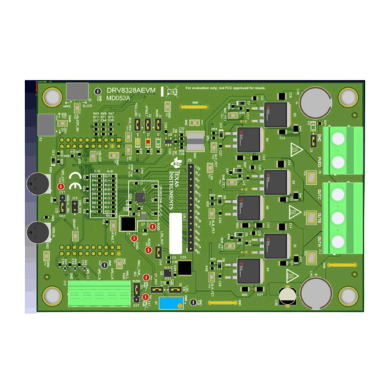
LaunchPad MCU and DRV8328. For step by step details on connecting the LAUNCHXL- F280049C + DRV8328AEVM, refer to Section Figure 1-1. DRV8328AEVM PCB Layout DRV8328xEVM User's Guide SLVUCD3A – NOVEMBER 2021 – REVISED AUGUST 2022 Submit Document Feedback Copyright © 2022 Texas Instruments Incorporated... -
Page 3: Quick Start Guide
6. Connect a Micro-USB cable from the computer into the Micro USB connector on the top of the LAUNCHXL- F280049C as shown in Figure 3-3. SLVUCD3A – NOVEMBER 2021 – REVISED AUGUST 2022 DRV8328xEVM User's Guide Submit Document Feedback Copyright © 2022 Texas Instruments Incorporated... -
Page 4: Hardware And Software Overview
For sensored applications, to connect the Hall sensor outputs to the Hall connectors on the DRV8328AEVM, push down on the respective terminals to open the sockets and insert the Hall sensor wires into connector J10. DRV8328xEVM User's Guide SLVUCD3A – NOVEMBER 2021 – REVISED AUGUST 2022 Submit Document Feedback Copyright © 2022 Texas Instruments Incorporated... - Page 5 LaunchPad firmware and GUI as well as the correct installment of the DRV8328AEVM to the J1/J3 and J2/J4 headers of the LaunchPad. SLVUCD3A – NOVEMBER 2021 – REVISED AUGUST 2022 DRV8328xEVM User's Guide Submit Document Feedback Copyright © 2022 Texas Instruments Incorporated...
-
Page 6: Led Lights
The fault LED will light up when the driver reports a fault, and the MCU LED (tied to GPIO59) can be used for debugging and validation. Table 3-1 shows the LED descriptions, with the LEDs that DRV8328xEVM User's Guide SLVUCD3A – NOVEMBER 2021 – REVISED AUGUST 2022 Submit Document Feedback Copyright © 2022 Texas Instruments Incorporated... -
Page 7: Drv8328Aevm Configurability And Switch Functions
3.4 DRV8328AEVM Configurability and Switch Functions The DRV8328AEVM includes a variety of user-selectable jumpers and unpopulated components on the PCB to choose user settings and evaluate the DRV8328A, DRV8328B, DRV8328C, or DRV8328D device. A summary of those selectable settings is listed in... - Page 8 DRV8328 used R1-R10 = 0-ohm, R11 – DRV8328C is populated on the EVM. R21 = DNP DRV8328D is populated DRV8328xEVM User's Guide SLVUCD3A – NOVEMBER 2021 – REVISED AUGUST 2022 Submit Document Feedback Copyright © 2022 Texas Instruments Incorporated...
- Page 9 Figure 3-6. User-adjustable jumpers, resistors, and switches on DRV8328AEVM 3.4.1 DRV8328A/B Compatibility The DRV8328AEVM default is the DRV8328A (Hardware variant), but can also be compatible with the DRV8328B. The main difference is that DRV8328A operates in 6x PWM mode and DRV8328B operates in 3x PWM mode. Figure 3-7 shows the default resistors to select the A/B variant when the DRV8328A or DRV8328B is used.
- Page 10 Hardware and Software Overview www.ti.com Figure 3-7. Resistors to populate for DRV8328A/B device Table 3-3 shows the resistors to be only populated as well as their pin and functions. Table 3-3. DRV8328A/B pinout, function, and populated resistors DRV8328A/B Pin Function...
-
Page 11: Interfacing Drv8328Aevm And Launchxl-F280049C Launchpad
5 V LaunchPad Supply POT_MCU/NC_49C PGA1/3/5_GND Not used GND connection Not used GPIO13/SCIBRX Not used VSENA ADCINA5 Phase A Voltage Sense SLVUCD3A – NOVEMBER 2021 – REVISED AUGUST 2022 DRV8328xEVM User's Guide Submit Document Feedback Copyright © 2022 Texas Instruments Incorporated... - Page 12 Hall sensor A from motor Not used SPIASOMI Not used nSLEEP_49C GPIO30 nSLEEP signal (active low) DRVOFF GPIO39 Active-high output to disable gate drivers DRV8328xEVM User's Guide SLVUCD3A – NOVEMBER 2021 – REVISED AUGUST 2022 Submit Document Feedback Copyright © 2022 Texas Instruments Incorporated...
- Page 13 If multiple signal paths are present, or no signal path is present, the device may not work as intended. SLVUCD3A – NOVEMBER 2021 – REVISED AUGUST 2022 DRV8328xEVM User's Guide Submit Document Feedback Copyright © 2022 Texas Instruments Incorporated...
-
Page 14: Hardware Setup
1. Ensure all resistors, jumpers, and switches are set up accordingly according to the device variant used. The DRV8328AEVM by default is populated with and configured for the DRV8328A. If using the DRV8328C or DRV8328D, please follow Section 3.4.2... -
Page 15: Firmware And Gui Application
MCU. Once complete, the “Hardware Connected” message appears at the bottom left hand corner as shown in Figure 5-2. SLVUCD3A – NOVEMBER 2021 – REVISED AUGUST 2022 DRV8328xEVM User's Guide Submit Document Feedback Copyright © 2022 Texas Instruments Incorporated... - Page 16 PWM Frequency (Hz) – 20000 • MCU Dead Time (ns) – 0 • Acceleration Delay (ms/1% duty cycle) – 21 DRV8328xEVM User's Guide SLVUCD3A – NOVEMBER 2021 – REVISED AUGUST 2022 Submit Document Feedback Copyright © 2022 Texas Instruments Incorporated...
-
Page 17: Drv8328Aevm Gui Quick Start Guide
1. Enter the PWM frequency in Hz using the “PWM Frequency (Hz)” text box. Press Enter. 2. Adjust the MCU dead time and Acceleration Delay values. For DRV8328A/B, it is recommended to use the DT potentiometer and set MCU dead time to 0 ns. - Page 18 • MCU Dead Time – Sets the MCU dead time to the PWM inputs in ns. Recommended to set DT to the minimum on the DRV8328A/B by setting placing 0-ohm resistor for R91. • Duty Cycle – Sets the duty cycle of the motor when potentiometer is disabled.
-
Page 19: Schematics
Spare C1 cap for DRV8328C/D INHA 1µF 1µF DRVOFF 6.3V 6.3V INHB INLB nFAULT nSLEEP Figure 6-2. DRV8328C/D variant select schematic SLVUCD3A – NOVEMBER 2021 – REVISED AUGUST 2022 DRV8328xEVM User's Guide Submit Document Feedback Copyright © 2022 Texas Instruments Incorporated... -
Page 20: Status Leds
LDO_OUT AVDD PVDD 10uF 100nF 0.1µF 10uF 100V 6.3V 100V 6.3V LDO_EN DELAY TPS7A1633QDGNRQ1 Figure 6-6. External 3.3V LDO schematic DRV8328xEVM User's Guide SLVUCD3A – NOVEMBER 2021 – REVISED AUGUST 2022 Submit Document Feedback Copyright © 2022 Texas Instruments Incorporated... -
Page 21: Power Stage And Mosfets
Hall Sensor Power Select +5V only allowed when launchpad generates voltage Figure 6-9. Hall Sensor and Hall Power Selection schematic SLVUCD3A – NOVEMBER 2021 – REVISED AUGUST 2022 DRV8328xEVM User's Guide Submit Document Feedback Copyright © 2022 Texas Instruments Incorporated... -
Page 22: Connectors, Selectors, And Analog Control Interface
DT (Pin 27 DRV8328A/B) DT = GND: t_Dead = 55 ns Valid VDSLVL range: 0.1V - 2.5V DT = Floating: t_Dead = 160 ns (DRV8328B) or 55 ns (DRV8328A) VDSLVL Select POT Voltage range: 0V - 2.538V DT = 10 k < R88 < 390 k: t_Dead = linear between 100 ns - 2000 ns... -
Page 23: Voltage Sense And Protection
Changes from Revision * (November 2021) to Revision A (August 2022) Page • Updated images to production version of DRV8328AEVM................SLVUCD3A – NOVEMBER 2021 – REVISED AUGUST 2022 DRV8328xEVM User's Guide Submit Document Feedback Copyright © 2022 Texas Instruments Incorporated... - Page 24 STANDARD TERMS FOR EVALUATION MODULES Delivery: TI delivers TI evaluation boards, kits, or modules, including any accompanying demonstration software, components, and/or documentation which may be provided together or separately (collectively, an “EVM” or “EVMs”) to the User (“User”) in accordance with the terms set forth herein.
- Page 25 www.ti.com Regulatory Notices: 3.1 United States 3.1.1 Notice applicable to EVMs not FCC-Approved: FCC NOTICE: This kit is designed to allow product developers to evaluate electronic components, circuitry, or software associated with the kit to determine whether to incorporate such items in a finished product and software developers to write software applications for use with the end product.
- Page 26 www.ti.com Concernant les EVMs avec antennes détachables Conformément à la réglementation d'Industrie Canada, le présent émetteur radio peut fonctionner avec une antenne d'un type et d'un gain maximal (ou inférieur) approuvé pour l'émetteur par Industrie Canada. Dans le but de réduire les risques de brouillage radioélectrique à...
- Page 27 www.ti.com EVM Use Restrictions and Warnings: 4.1 EVMS ARE NOT FOR USE IN FUNCTIONAL SAFETY AND/OR SAFETY CRITICAL EVALUATIONS, INCLUDING BUT NOT LIMITED TO EVALUATIONS OF LIFE SUPPORT APPLICATIONS. 4.2 User must read and apply the user guide and other available documentation provided by TI regarding the EVM prior to handling or using the EVM, including without limitation any warning or restriction notices.
- Page 28 Notwithstanding the foregoing, any judgment may be enforced in any United States or foreign court, and TI may seek injunctive relief in any United States or foreign court. Mailing Address: Texas Instruments, Post Office Box 655303, Dallas, Texas 75265 Copyright © 2019, Texas Instruments Incorporated...
- Page 29 TI products. TI’s provision of these resources does not expand or otherwise alter TI’s applicable warranties or warranty disclaimers for TI products. TI objects to and rejects any additional or different terms you may have proposed. IMPORTANT NOTICE Mailing Address: Texas Instruments, Post Office Box 655303, Dallas, Texas 75265 Copyright © 2022, Texas Instruments Incorporated...
Need help?
Do you have a question about the DRV8328A and is the answer not in the manual?
Questions and answers