Table of Contents
Advertisement
Quick Links
www.ti.com
User's Guide
DRV8317HEVM User's Guide
This document is provided with the
DRV8317 4.5-V to 20-V Three-Phase Smart Gate
EVM and shows how to set up and power the board with the
F280049C LaunchPad™ development
The DRV8317HEVM comes automatically populated with and configured for the DRV8317H hardware
device. It is also compatible for the DRV8317S variant, but the user will need to modify the board to
make it compatible for the SPI variant (see
Warnings..........................................................................................................................................................2
2
Introduction.............................................................................................................................................................................3
Guide....................................................................................................................................................................4
4.1 Hardware Connections Overview - DRV8317HEVM + LAUNCHXL-F280049C...............................................................
4.2 Connection Details.............................................................................................................................................................
Lights..........................................................................................................................................................................7
5 Hardware Setup....................................................................................................................................................................
Application.............................................................................................................................................15
6.1 C2000 InstaSPIN Universal GUI......................................................................................................................................
Identification...........................................................................................................................................................15
6.3 Sensorless-FOC Commutation........................................................................................................................................
7
Schematics............................................................................................................................................................................19
7.1 Main Supply.....................................................................................................................................................................
7.2
DRV8317H/S....................................................................................................................................................................20
7.5 LaunchPad Connections..................................................................................................................................................
7.6 Connectors & Interface....................................................................................................................................................
8 Revision History...................................................................................................................................................................
Trademarks
All trademarks are the property of their respective owners.
SLVUCL3 - DECEMBER 2022
Submit Document Feedback
DRV8317HEVM customer evaluation module (EVM)
kit).
Section
Table of Contents
Overview.........................................................................................................................................5
Resistors.................................................................................................8
only).............................................................................................................................17
VREF.......................................................................................................................................21
Protection...................................................................................................................23
Copyright © 2022 Texas Instruments Incorporated
ABSTRACT
Driver. This User's Guide details the implementation of the
LAUNCHXL-F280049C (C2000 Piccolo MCU
Note
4.4).
Techniques..........................................................................17
Table of Contents
to evaluate the
5
5
14
15
16
19
22
22
23
DRV8317HEVM User's Guide
1
Advertisement
Table of Contents

Subscribe to Our Youtube Channel
Related Manuals for Texas Instruments DRV8317HEVM


Summary of Contents for Texas Instruments DRV8317HEVM
-
Page 1: Table Of Contents
Note The DRV8317HEVM comes automatically populated with and configured for the DRV8317H hardware device. It is also compatible for the DRV8317S variant, but the user will need to modify the board to make it compatible for the SPI variant (see Section 4.4). -
Page 2: Cautions And Warnings
Component Name Manufacturer Part Number Candidate Listed Chemical Identity Concentration Chemical (CAS#) PCB terminal block - Phoenix Contact 1935190 Lead 7439-92-1 PT 1,5/ 5-5,0-H DRV8317HEVM User's Guide SLVUCL3 – DECEMBER 2022 Submit Document Feedback Copyright © 2022 Texas Instruments Incorporated... -
Page 3: Introduction
DRV8317 to control the BLDC motor. This document serves as a startup guide for the DRV8317HEVM + LAUNCHXL-F280049C BLDC motor control demo kit. It also is intended to help engineers design, implement, and validate reference hardware and software for the LaunchPad MCU and DRV8317. -
Page 4: Quick Start Guide
3 Quick Start Guide The DRV8317HEVM requires a power supply with a recommended operating range from 4.5-V to 20-V. To setup and power the EVM, follow the sequence below: 1. Connect the power supply ground to the PGND of the 2-pin power connector J5 and the power supply positive terminal to the VBAT pin of J5. -
Page 5: Hardware And Software Overview
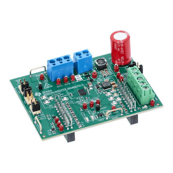
4.2 Connection Details Figure 4-2 shows the power supply and motor connections made to the DRV8317HEVM in order to spin a 3-phase sensored or sensorless Brushless-DC motor. A 4.5-V to 20-V power supply or battery is connected to the VBAT and GND terminals. The three phases of the BLDC motor connect directly to the OUTA, OUTB, and OUTC terminals of the screw terminal provided on the DRV8317HEVM. - Page 6 Micro-USB cable is plugged in to the LAUNCHXL-F280049C to provide communication between the LaunchPad firmware and GUI as well as the correct installment of the DRV8317HEVM to the J1/J3 and J2/J4 headers of the LaunchPad. DRV8317HEVM User's Guide SLVUCL3 –...
-
Page 7: Led Lights
USB cable is plugged in to the LaunchPad. The DRV8317HEVM has 4 status LEDs on the board. By default, the VM and V_BUCK LEDs will light up when the board is powered on. The fault LED will light up when the driver reports a fault, and the MCU LED (tied to GPIO59) can be used for debugging and validation. -
Page 8: Drv8317Hevm Configurability - Jumpers And Resistors
Figure 4-4. DRV8317HEVM LEDs 4.4 DRV8317HEVM Configurability – Jumpers and Resistors The DRV8317HEVM includes a variety of user-selectable jumpers and unpopulated components on the PCB to choose user settings and evaluate the DRV8317H or the DRV8317S device. A summary of those selectable... - Page 9 Hardware and Software Overview Table 4-2. Description of user selectable settings on DRV8317HEVM (H variant defaults in bold) (continued) Setting Name Description Position Function SLEW select (DRV8317H only) Use J9 J9 = Bottom 25 V/us jumper to select desired...
- Page 10 Figure 4-5. User-selectable jumpers and DNP components on DRV8317HEVM 4.4.1 DRV8317H Compatibility The DRV8317HEVM default is the DRV8317H (Hardware variant), which can be used to spin a 3-phase Brushless-DC motor with selectable modes configured with hardware settings as shown in Table 4-3.
- Page 11 J8 = Bottom 0.25 V/A 4.4.2 DRV8317S Compatibility The DRV8317HEVM is compatible with the DRV8317S (SPI variant) to spin a 3-phase Brushless-DC motor. The DRV8317S replaces the hardware settings (MODE, SLEW, and GAIN) with 4 SPI signals: SDI, SDO, SCLK, and nSCS.
- Page 12 Hardware and Software Overview www.ti.com Table 4-5. Connections for Header J3 on DRV8317HEVM (DNP in bold) (continued) J3 Pin Number DRV8317HEVM Function LAUNCHXL-F280049C Function Description Not used GPIO13/SCIBRX Not used VSENA ADCINA5 Phase A Voltage Sense HALLC GPIO40/SCIBTX Hall sensor C from motor...
- Page 13 Hardware and Software Overview Table 4-6. Connections for Header J4 on DRV8317HEVM (continued) J4 Pin Number DRV8317HEVM Function LAUNCHXL-F280049C Function Description Not used GPIO18/XCLKOUT (not Not used connected) Not used GPIO23/LED4 LED reserved on LaunchPad CSA_REF (DNP) GPIO25 For internal use only...
-
Page 14: Hardware Setup
The hardware required to run the motor control is the LAUNCHXL-F280049C LaunchPad development kit, the DRV8317HEVM, a Micro-USB cable, and a power supply with a DC output from 4.5-V to 20-V. Follow these steps to set up the evaluation module: 1. -
Page 15: Firmware And Gui Application
Library of motor solutions. The firmware includes motor identification and a sensorless FOC algorithm to spin the motor. The firmware uses the DRV8317HEVM InstaSPIN Universal GUI to run the algorithm and includes tabs to read from and write to the DRV8317 SPI registers (DRV8317S only). -
Page 16: Sensorless-Foc Commutation
Figure 6-2. C2000 InstaSPIN Universal GUI Running motor identification Figure 6-3. Motor identification complete using the DRV8317HEVM InstaSPIN GUI 6.3 Sensorless-FOC Commutation 1. To spin the motor with sensorless FOC, check the “Run” box again. The motor will spin with sinusoidal current at the speedRef (Hz) value in the GUI, which is automatically set to 20.0 Hz. -
Page 17: Torque Control, Speed Control, And Advanced Modulation Techniques
6.4 Torque Control, Speed Control, and Advanced Modulation Techniques To implement more advanced modulation techniques such as torque control, speed control, and algorithms such as MTPA, Field-weakening, and PowerWarp (EPL) using the DRV8317HEVM InstaSPIN Universal GUI, please consult the MotorControl SDK InstaSPIN Lab Guide found in MotorControl SDK. - Page 18 Firmware and GUI Application www.ti.com Figure 6-5. DRV8317HEVM InstaSPIN GUI SPI Control Registers DRV8317HEVM User's Guide SLVUCL3 – DECEMBER 2022 Submit Document Feedback Copyright © 2022 Texas Instruments Incorporated...
-
Page 19: Schematics
Schematics 7 Schematics 7.1 Main Supply Figure 7-1. Main Supply schematic SLVUCL3 – DECEMBER 2022 DRV8317HEVM User's Guide Submit Document Feedback Copyright © 2022 Texas Instruments Incorporated... -
Page 20: Drv8317H/S
Schematics www.ti.com 7.2 DRV8317H/S Figure 7-2. DRV8317H/S schematic DRV8317HEVM User's Guide SLVUCL3 – DECEMBER 2022 Submit Document Feedback Copyright © 2022 Texas Instruments Incorporated... -
Page 21: Buck Regulator And Vref
Schematics 7.3 3.3V Buck Regulator and VREF Figure 7-3. 3.3V Buck Regulator and VREF schematic SLVUCL3 – DECEMBER 2022 DRV8317HEVM User's Guide Submit Document Feedback Copyright © 2022 Texas Instruments Incorporated... -
Page 22: Launchpad Connections
Schematics www.ti.com 7.5 LaunchPad Connections Figure 7-4. LaunchPad Connections schematic 7.6 Connectors & Interface Figure 7-5. Connectors & Interface schematic DRV8317HEVM User's Guide SLVUCL3 – DECEMBER 2022 Submit Document Feedback Copyright © 2022 Texas Instruments Incorporated... -
Page 23: Status Leds, Voltage Sense, And Protection
8 Revision History NOTE: Page numbers for previous revisions may differ from page numbers in the current version. DATE REVISION NOTES Initial Release December 2022 SLVUCL3 – DECEMBER 2022 DRV8317HEVM User's Guide Submit Document Feedback Copyright © 2022 Texas Instruments Incorporated... - Page 24 STANDARD TERMS FOR EVALUATION MODULES Delivery: TI delivers TI evaluation boards, kits, or modules, including any accompanying demonstration software, components, and/or documentation which may be provided together or separately (collectively, an “EVM” or “EVMs”) to the User (“User”) in accordance with the terms set forth herein.
- Page 25 www.ti.com Regulatory Notices: 3.1 United States 3.1.1 Notice applicable to EVMs not FCC-Approved: FCC NOTICE: This kit is designed to allow product developers to evaluate electronic components, circuitry, or software associated with the kit to determine whether to incorporate such items in a finished product and software developers to write software applications for use with the end product.
- Page 26 www.ti.com Concernant les EVMs avec antennes détachables Conformément à la réglementation d'Industrie Canada, le présent émetteur radio peut fonctionner avec une antenne d'un type et d'un gain maximal (ou inférieur) approuvé pour l'émetteur par Industrie Canada. Dans le but de réduire les risques de brouillage radioélectrique à...
- Page 27 www.ti.com EVM Use Restrictions and Warnings: 4.1 EVMS ARE NOT FOR USE IN FUNCTIONAL SAFETY AND/OR SAFETY CRITICAL EVALUATIONS, INCLUDING BUT NOT LIMITED TO EVALUATIONS OF LIFE SUPPORT APPLICATIONS. 4.2 User must read and apply the user guide and other available documentation provided by TI regarding the EVM prior to handling or using the EVM, including without limitation any warning or restriction notices.
- Page 28 Notwithstanding the foregoing, any judgment may be enforced in any United States or foreign court, and TI may seek injunctive relief in any United States or foreign court. Mailing Address: Texas Instruments, Post Office Box 655303, Dallas, Texas 75265 Copyright © 2019, Texas Instruments Incorporated...
- Page 29 TI products. TI’s provision of these resources does not expand or otherwise alter TI’s applicable warranties or warranty disclaimers for TI products. TI objects to and rejects any additional or different terms you may have proposed. IMPORTANT NOTICE Mailing Address: Texas Instruments, Post Office Box 655303, Dallas, Texas 75265 Copyright © 2022, Texas Instruments Incorporated...
Need help?
Do you have a question about the DRV8317HEVM and is the answer not in the manual?
Questions and answers