Table of Contents
Advertisement
Quick Links
www.ti.com
EVM User's Guide: DRV8376EVM
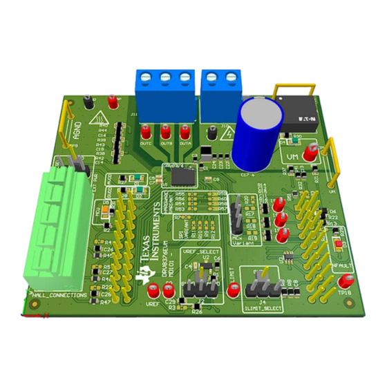
DRV8376 Evaluation Module
Description
The DRV8376EVM is a integrated driver IC evaluation
module for three-phase motor driver applications
and provides single-chip power stage design for
customers driving 4.5V to 65V brushless DC motors.
Along with the hardware of the DRV8376, the
TMS320F280049C microcontroller-based board has
reference software that sends necessary signals to
the DRV8376 to spin a 3-phase Brushless-DC motor.
GUIComposer software allows the user to program
settings, enable the motor to spin, and monitor the
system from fault conditions.
Get Started
1. Order the
DRV8376EVM
2. Download the comprehensive reference design
files from the
DRV8376EVM tool page
3. Refer to the
DRV8376 Three-Phase Integrated
FET Motor Driver
data sheet or refer to E2E for
questions and support
SLVUD20 – OCTOBER 2024
Submit Document Feedback
and
TMS320F280049C
DRV8376EVM
Copyright © 2024 Texas Instruments Incorporated
Features
•
4.5V to 65V operating voltage (70V abs max)
•
High output current capability: 4.5A peak
•
AVDD and GVDD regulators
•
Integrated CSAs for three-phase low-side current
measurement
•
Supply and fault LEDs
•
C2000 (LAUNCHXL-F280049C) sensored
trapezoidal firmware available
Applications
•
Brushless-DC (BLDC) motor modules
•
HVAC motors
•
Office automation machines
•
Factory automation and robotics
•
Wireless antenna motor
•
ATMs (Automated Teller Machines)
•
Drones
Description
DRV8376 Evaluation Module
1
Advertisement
Table of Contents

Related Manuals for Texas Instruments DRV8376


Summary of Contents for Texas Instruments DRV8376
- Page 1 • AVDD and GVDD regulators customers driving 4.5V to 65V brushless DC motors. • Integrated CSAs for three-phase low-side current Along with the hardware of the DRV8376, the measurement TMS320F280049C microcontroller-based board has • Supply and fault LEDs reference software that sends necessary signals to •...
-
Page 2: Kit Contents
This document is intended for the engineers involved in the design, implementation, and validation of DRV8376 and TMS320F280049C reference software. The scope of this document is to provide the user with a guide to evaluate the DRV8376 device with a TMS320F280049C isolated board. This document covers the hardware connections required between boards and external motor and supplies. -
Page 3: Quick Start
2-2. Make sure the power supply input and phase outputs of the DRV8376EVM are facing the opposite direction of the micro-USB on the LaunchXL-F280049C. SLVUD20 – OCTOBER 2024 DRV8376 Evaluation Module Submit Document Feedback Copyright © 2024 Texas Instruments Incorporated... - Page 4 High voltage. Electric shock is possible when connecting board to live wire. The board must be handled with care by a professional. For safety, use of isolated test equipment with overvoltage and overcurrent protection is highly recommended. DRV8376 Evaluation Module SLVUD20 – OCTOBER 2024 Submit Document Feedback Copyright © 2024 Texas Instruments Incorporated...
-
Page 5: Led Indicators
GVDD turn on once power is supplied to the board. The MCU LED turns on once the GUI or Firmware runs on the LaunchXL-F280049C while the DRV8376EVM is connected. The NFAULT status LED turns on as soon as a driver fault occurs. SLVUD20 – OCTOBER 2024 DRV8376 Evaluation Module Submit Document Feedback Copyright © 2024 Texas Instruments Incorporated... -
Page 6: Jumper Information
For externally supplied hall power, supply the power to TP12 and make sure there is a jumper where the blue rectangle is, as seen in the figure above. DRV8376 Evaluation Module SLVUD20 – OCTOBER 2024 Submit Document Feedback Copyright © 2024 Texas Instruments Incorporated... - Page 7 Hardware VREF Figure 2-5. DRV8376EVM VREF Selection Location Figure 2-6. DRV8376EVM VREF Configuration SLVUD20 – OCTOBER 2024 DRV8376 Evaluation Module Submit Document Feedback Copyright © 2024 Texas Instruments Incorporated...
- Page 8 Hardware www.ti.com ILIMIT Figure 2-7. DRV8376EVM ILIMIT Selection Location Figure 2-8. DRV8376EVM ILIMIT Configuration DRV8376 Evaluation Module SLVUD20 – OCTOBER 2024 Submit Document Feedback Copyright © 2024 Texas Instruments Incorporated...
- Page 9 Phase B voltage sense Not used ADCINB3/VDAC Not used VSENA ADCINB1 Phase A Voltage Sense SCLK SPIACLK SPI clock (DRV8376 SPI Variant only) ISENA ADCINB2 Phase A current sense nFAULT (DNP) ADCINC4 For internal use only ISENB ADCINC0 Phase B current sense...
- Page 10 Not used XRSn Not used INLC/HNC GPIO5/PWM3B PWM used to switch Phase C lowside FET SPIAPICO SPI data input (DRV8376 SPI Variant only) HALLA GPIO58 HALL sensor A from motor SPIAPOCI SPI data output (DRV8376 SPI Variant only) HALLB GPIO30...
-
Page 11: Test Points
Hardware 2.5 Test Points Figure 2-11. DRV8376EVM Test Points All the test points available on the DRV8376EVM are shown in Figure 2-11. SLVUD20 – OCTOBER 2024 DRV8376 Evaluation Module Submit Document Feedback Copyright © 2024 Texas Instruments Incorporated... - Page 12 DRV8376EVM 4.5A Connect to AGND Populate R59 with 0 ohm resistor or short Connect to GVDD Populate R55 with 0 ohm resistor or short DRV8376 Evaluation Module SLVUD20 – OCTOBER 2024 Submit Document Feedback Copyright © 2024 Texas Instruments Incorporated...
- Page 13 2-13. Make sure the resistors for hardware variant and MCx variant are unpopulated or DNP. Figure 2-13. SPI Configuration Resistors Once the appropriate resistors have been populated, the DRV8376 IC can be configured through SPI. SLVUD20 – OCTOBER 2024 DRV8376 Evaluation Module Submit Document Feedback Copyright ©...
- Page 14 Make sure the resistors for SPI variant are unpopulated or DNP, that R17, R18, and R19 are populated with 0 ohm resistors or shorted, and R20 is populated with a 5.1k ohm resistor. The MCx variant of the DRV8376 IC utilizes the Hardware variant resistors for configuration of MODE, GAIN_SLEW_tLOCK, DIR, and ADVANCE.
- Page 15 Populate R56 with 100k ohm resistor 22k ohm to GVDD 25° Populate R56 with 22k ohm resistor Connected to GVDD 30° Populate R56 with 0 ohm resistor or short SLVUD20 – OCTOBER 2024 DRV8376 Evaluation Module Submit Document Feedback Copyright © 2024 Texas Instruments Incorporated...
- Page 16 10. If direction change is needed, then toggle the direction in the GUI, observe the motor slowing down to a stop, and then spinning in opposite direction. 11. Disable the motor by switching the Output Enable to OFF. DRV8376 Evaluation Module SLVUD20 – OCTOBER 2024 Submit Document Feedback Copyright © 2024 Texas Instruments Incorporated...
- Page 17 Tied to G VDD: GAIN = 2.5 V/A, SLEW = 0.25V/ns, LOCK_DET_TIME = 500 ms Figure 4-1. DRV8376EVM Schematic - Main supply, Voltage Sense & Protection, and Connectors & Interface SLVUD20 – OCTOBER 2024 DRV8376 Evaluation Module Submit Document Feedback Copyright © 2024 Texas Instruments Incorporated...
-
Page 18: Status Leds
These assemblies must be clean and free from flux and all contaminants. Use of no clean flux is not acceptable. Assembly Note These assemblies must comply with workmanship standards IPC-A-610 Class 2, unless otherwise specified. Figure 4-3. DRV8376EVM - Miscellaneous DRV8376 Evaluation Module SLVUD20 – OCTOBER 2024 Submit Document Feedback Copyright © 2024 Texas Instruments Incorporated... -
Page 19: Pcb Layouts
Hardware Design Files 4.2 PCB Layouts Figure 4-4. DRV8376EVM PCB Layer 1 Figure 4-5. DRV8376EVM PCB Layer 2 SLVUD20 – OCTOBER 2024 DRV8376 Evaluation Module Submit Document Feedback Copyright © 2024 Texas Instruments Incorporated... - Page 20 Hardware Design Files www.ti.com Figure 4-6. DRV8376EVM PCB Layer 3 Figure 4-7. DRV8376EVM PCB Layer 4 DRV8376 Evaluation Module SLVUD20 – OCTOBER 2024 Submit Document Feedback Copyright © 2024 Texas Instruments Incorporated...
- Page 21 Hardware Design Files Figure 4-8. DRV8376EVM PCB Layer 5 Figure 4-9. DRV8376EVM PCB Layer 6 SLVUD20 – OCTOBER 2024 DRV8376 Evaluation Module Submit Document Feedback Copyright © 2024 Texas Instruments Incorporated...
- Page 22 Hardware Design Files www.ti.com Figure 4-10. DRV8376EVM PCB Layer 7 DRV8376 Evaluation Module SLVUD20 – OCTOBER 2024 Submit Document Feedback Copyright © 2024 Texas Instruments Incorporated...
-
Page 23: Bill Of Materials (Bom)
J1, J3, J6 Header, 2.54mm, 1x1, Gold, TH TSW-101-08-G-S Samtec Header, 2.54mm,1x1, J2, J4, J7, J13 Header, 2.54mm, 3x1, Tin, TH 68001-403HLF Header, 2.54mm,3x1, SLVUD20 – OCTOBER 2024 DRV8376 Evaluation Module Submit Document Feedback Copyright © 2024 Texas Instruments Incorporated... - Page 24 RES, 100 k, 0.1%, 0.1 W, AEC-Q200 Grade 0, ERA-3AEB104V Panasonic 0603 0603 R53, R54, R55,R57, 47.0k RES, 47.0 k, 0.5%, 0.15 W, AEC-Q200 Grade 0, MCT0603MD4702DP500 Vishay/Beyschlag 0603 R58, R59 0603 DRV8376 Evaluation Module SLVUD20 – OCTOBER 2024 Submit Document Feedback Copyright © 2024 Texas Instruments Incorporated...
- Page 25 Automotive 20ppm / degC Max, 100uA, REF3130AQDBZRQ1 Texas Instruments DBZ0003A SOT23-3 Series VoltageReference, DBZ0003A (SOT-23-3) 4-Channel ESD Solution for High-Speed TPD4S009DCKR Texas Instruments DCK0006A Differential Interface, DCK0006A(SOT-SC70-6) SLVUD20 – OCTOBER 2024 DRV8376 Evaluation Module Submit Document Feedback Copyright © 2024 Texas Instruments Incorporated...
-
Page 26: Additional Information
Additional Information www.ti.com 5 Additional Information 5.1 Trademarks LaunchPad ™ is a trademark of Texas Instruments. Google Chrome ® is a registered trademark of Google LLC. All trademarks are the property of their respective owners. DRV8376 Evaluation Module SLVUD20 – OCTOBER 2024 Submit Document Feedback Copyright ©... - Page 27 STANDARD TERMS FOR EVALUATION MODULES Delivery: TI delivers TI evaluation boards, kits, or modules, including any accompanying demonstration software, components, and/or documentation which may be provided together or separately (collectively, an “EVM” or “EVMs”) to the User (“User”) in accordance with the terms set forth herein.
- Page 28 www.ti.com Regulatory Notices: 3.1 United States 3.1.1 Notice applicable to EVMs not FCC-Approved: FCC NOTICE: This kit is designed to allow product developers to evaluate electronic components, circuitry, or software associated with the kit to determine whether to incorporate such items in a finished product and software developers to write software applications for use with the end product.
- Page 29 www.ti.com Concernant les EVMs avec antennes détachables Conformément à la réglementation d'Industrie Canada, le présent émetteur radio peut fonctionner avec une antenne d'un type et d'un gain maximal (ou inférieur) approuvé pour l'émetteur par Industrie Canada. Dans le but de réduire les risques de brouillage radioélectrique à...
- Page 30 www.ti.com EVM Use Restrictions and Warnings: 4.1 EVMS ARE NOT FOR USE IN FUNCTIONAL SAFETY AND/OR SAFETY CRITICAL EVALUATIONS, INCLUDING BUT NOT LIMITED TO EVALUATIONS OF LIFE SUPPORT APPLICATIONS. 4.2 User must read and apply the user guide and other available documentation provided by TI regarding the EVM prior to handling or using the EVM, including without limitation any warning or restriction notices.
- Page 31 Notwithstanding the foregoing, any judgment may be enforced in any United States or foreign court, and TI may seek injunctive relief in any United States or foreign court. Mailing Address: Texas Instruments, Post Office Box 655303, Dallas, Texas 75265 Copyright © 2023, Texas Instruments Incorporated...
-
Page 32: Important Notice
TI products. TI’s provision of these resources does not expand or otherwise alter TI’s applicable warranties or warranty disclaimers for TI products. TI objects to and rejects any additional or different terms you may have proposed. IMPORTANT NOTICE Mailing Address: Texas Instruments, Post Office Box 655303, Dallas, Texas 75265 Copyright © 2024, Texas Instruments Incorporated...
Need help?
Do you have a question about the DRV8376 and is the answer not in the manual?
Questions and answers