
Subscribe to Our Youtube Channel
Related Manuals for Teknik Clifton Place 5421113


Summary of Contents for Teknik Clifton Place 5421113
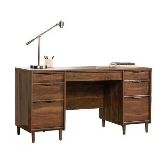
- Page 1 Teknik www.teknikoffice.co.uk Business or pleasure. Works both ways. Executive Desk Clifton Place Collection | Model 5421113 NOTE: THIS INSTRUCTION BOOKLET CONTAINS IMPORTANT SAFETY INFORMATION. PLEASE READ AND KEEP FOR FUTURE REFERENCE.
- Page 2 Table of Contents Assembly Tools Required Part Identifi cation No. 2 Phillips Screwdriver Tip Shown Actual Size Hardware Identifi cation Assembly Steps 5-38 Hammer Not actual size Français 39-43 Español 44-48 Skip the power trip. Safety 49-50 This time. Warranty Part Identifi...
- Page 3 Now you know Part Identifi cation our ABCs. å While not all parts are labeled, some of the parts will have a label or an inked letter on the edge to help distinguish similar parts from each other. Use this part identifi cation to help identify similar parts. Hardware Identifi...
- Page 4 Hardware Identifi cation å Screws are shown actual size. You may receive extra hardware with your unit. RIGHT CABINET LEFT CABINET RAIL - 4 RAIL - 4 RIGHT DRAWER LEFT DRAWER SLIDE - 4 SLIDE - 4 SHORT WOOD ANGLED HEAD STRAIGHT HEAD LARGE HIDDEN SMALL HIDDEN...
- Page 5 Step 1 Assemble your unit on a carpeted fl oor or on the empty carton to avoid scratching your unit or the fl oor. å Turn six ANGLED HEAD CAM SCREWS (3) into the LEFT END (B). å Push two LONG WOOD DOWELS (6) into the short edge of the LEFT END (B). å...
- Page 6 Step 2 Turn six ANGLED HEAD CAM SCREWS (3) into the LEFT UPRIGHT (C). å Fasten two RIGHT CABINET RAILS (II) to the LEFT UPRIGHT (C). Use six BLACK 1/2" FLAT HEAD SCREWS (18) å through the 2nd, 3rd, and 5th holes as shown. Separate a LONG EXTENSION SLIDE (FF) from a LONG EXTENSION RAIL (EE) as shown in the upper diagram.
- Page 7 Step 3 Flip the LEFT UPRIGHT (C) over. å Turn three ANGLED HEAD CAM SCREWS (3) into the LEFT UPRIGHT (C). å Push two LONG WOOD DOWELS (6) into the short edge of the LEFT UPRIGHT (C). å Separate a SHORT EXTENSION SLIDE (HH) from a SHORT EXTENSION RAIL (GG) as shown in the upper diagram. å...
- Page 8 Step 4 Push fourteen LONG WOOD DOWELS (6) into a BACK (F), BOTTOM (H), å and two BRACES (K). Turn two ANGLED HEAD CAM SCREWS (3) into the BACK (F). å Insert a GROMMET (9) into the large hole in the BOTTOM (H). å...
- Page 9 Step 5 Push two LARGE HIDDEN CAMS (1) into a BOTTOM (H). å Fasten the BOTTOM (H) to a BACK (F). Tighten two å LARGE HIDDEN CAMS. NOTE: Be sure the WOOD DOWELS in the BOTTOM å insert into the BACK. Repeat this step for the other BACK (F), and BOTTOM (H).
- Page 10 Step 6 Push six LARGE HIDDEN CAMS (1) into a BACK (F), å BOTTOM (H), and two BRACES (K). Fasten the LEFT END (B) to the BACK (F) and BOTTOM (H). å Tighten four LARGE HIDDEN CAMS. NOTE: Be sure the WOOD DOWELS in the BACK and å...
- Page 11 Step 7 Push six LARGE HIDDEN CAMS (1) into the BACK (F), å BOTTOM (H), and BRACES (K). Fasten the LEFT UPRIGHT (C) to the BACK (F), BOTTOM (H), å and BRACES (K). Tighten six LARGE HIDDEN CAMS. NOTE: Be sure the WOOD DOWELS in the BACK, BOTTOM, å...
- Page 12 Step 8 Turn and tighten four FEET (M) into the BOTTOM (H). å Remember: Righty tighty. Lefty loosey. Page 12...
- Page 13 Step 9 Push four SHORT WOOD DOWELS (5) into the BOTTOM (H). å Fasten two BOTTOM MOLDINGS (L) to the BOTTOM (H). Use å four 1-1/8" FLAT HEAD SCREWS (16). 1-1/8" FLAT HEAD SCREW (4 used in this step) Page 13...
- Page 14 Step 10 Turn four LEVELERS (7) into the FEET (M). å NOTE: The LEVELERS will be adjusted in the last step. å Page 14...
- Page 15 Step 11 Turn six ANGLED HEAD CAM SCREWS (3) into the RIGHT END (A). å Push two LONG WOOD DOWELS (6) into the short edge of the RIGHT END (A). å Fasten two RIGHT CABINET RAILS (II) to the RIGHT END (A). Use six BLACK 1/2" FLAT HEAD SCREWS (18) through the å...
- Page 16 Step 12 Turn six ANGLED HEAD CAM SCREWS (3) into the RIGHT UPRIGHT (D). å Fasten two LEFT CABINET RAILS (JJ) to the RIGHT UPRIGHT (D). Use six BLACK 1/2" FLAT HEAD SCREWS (18) å through the 2nd, 3rd, and 5th holes as shown. Separate a LONG EXTENSION SLIDE (FF) from a LONG EXTENSION RAIL (EE) as shown in the upper diagram.
- Page 17 Step 13 Flip the RIGHT UPRIGHT (D) over. å Turn three ANGLED HEAD CAM SCREWS (3) into the RIGHT UPRIGHT (D). å Push two LONG WOOD DOWELS (6) into the short edge of the RIGHT UPRIGHT (D). å Separate a SHORT EXTENSION SLIDE (HH) from a SHORT EXTENSION RAIL (GG) as shown in the upper diagram. å...
- Page 18 Step 14 Push six LARGE HIDDEN CAMS (1) into a BACK (F), å BOTTOM (H), and two BRACES (K). Fasten the RIGHT END (A) to the BACK (F) and BOTTOM (H). å Tighten four LARGE HIDDEN CAMS. NOTE: Be sure the WOOD DOWELS in the BACK and å...
- Page 19 Step 15 Push six LARGE HIDDEN CAMS (1) into the BACK (F), å BOTTOM (H), and BRACES (K). Fasten the RIGHT UPRIGHT (D) to the BACK (F), å BOTTOM (H), and BRACES (K). Tighten six LARGE HIDDEN CAMS. NOTE: Be sure the WOOD DOWELS in the BACK, å...
- Page 20 Step 16 Turn and tighten four FEET (M) into the BOTTOM (H). å Push four SHORT WOOD DOWELS (5) into the BOTTOM (H). å Fasten two BOTTOM MOLDINGS (L) to the BOTTOM (H). Use å four 1-1/8" FLAT HEAD SCREWS (16). 1-1/8"...
- Page 21 Step 17 Turn four LEVELERS (7) into the FEET (M). å Now might be a NOTE: The LEVELERS will be adjusted in the last step. å good time to refresh your drink. Page 21...
- Page 22 Step 18 Turn two ANGLED HEAD CAM SCREWS (3) into the å Angled head MODESTY PANEL (G). Push six LONG WOOD DOWELS (6) into the edges of the å MODESTY PANEL (G) and MODESTY PANEL SHELF (DD). Page 22...
- Page 23 Step 19 Push two LARGE HIDDEN CAMS (1) into the MODESTY å PANEL SHELF (DD). Fasten the MODESTY PANEL SHELF (DD) to the MODESTY å PANEL (G). Tighten two LARGE HIDDEN CAMS. NOTE: Be sure the WOOD DOWEL in the MODESTY PANEL å...
- Page 24 Step 20 This step will require 2 people to assemble. å Push six LARGE HIDDEN CAMS (1) into the MODESTY å PANEL (G) and MODESTY PANEL SHELF (DD). Stand the unit pedestals onto their FEET. å Fasten the MODESTY PANEL (G) and MODESTY PANEL å...
- Page 25 Step 21 Push fourteen LARGE HIDDEN CAMS (1) into the å ENDS (A and B), UPRIGHTS (C and D), BACKS (F), and MODESTY PANEL (G). Arrow Arrow Arrow The arrow must be pointing up. The arrow must be pointing up. Page 25...
- Page 26 Step 22 Push six SHORT WOOD DOWELS (5) into the TOP (E). å Fasten the TOP MOLDINGS (I and J) to the TOP (E). Use å seven 1-1/8" FLAT HEAD SCREWS (16). NOTE: You may want to leave the screws slightly loose so å...
- Page 27 Step 23 Turn fourteen ANGLED HEAD CAM SCREWS (3) into å Angled head the TOP (E). (14 used) Page 27...
- Page 28 Step 24 Fasten the TOP (E) to the ENDS (A and B), UPRIGHTS (C å and D), and MODESTY PANEL (G). Tighten fourteen LARGE HIDDEN CAMS (1). NOTE: Be sure the WOOD DOWELS in the ENDS, UPRIGHTS, å and MODESTY PANEL insert into the holes in the TOP. Tighten the SCREWS in the TOP MOLDINGS.
- Page 29 Step 25 Turn twenty-four STRAIGHT HEAD CAM SCREWS (4) å into the DRAWER FRONTS (Q, R, and S). Straight head (24 used) Page 29...
- Page 30 Step 26 The arrow must point toward the edge of the board. Arrow Groove (8 used) Push four SMALL HIDDEN CAMS (2) into the SMALL Slide the DRAWER BOTTOM (CC) into the grooves å å DRAWER SIDES (T and V). in the SMALL DRAWER SIDES (T and V) and DRAWER FRONT (Q).
- Page 31 Step 27 The arrow must point toward the edge of the board. Arrow Groove (8 used) Push four SMALL HIDDEN CAMS (2) into the Slide the DRAWER BOTTOM (CC) into the grooves in the å å DRAWER SIDES (W and Y). DRAWER SIDES (W and Y) and DRAWER FRONT (R).
- Page 32 Step 28 The arrow must point toward the edge of the board. Arrow Groove (8 used) Slide the DRAWER BOTTOM (CC) into the grooves in Push four SMALL HIDDEN CAMS (2) into the LARGE å å the LARGE DRAWER SIDES (Z and BB) and LARGE DRAWER SIDES (Z and BB).
- Page 33 Step 29 Fasten a PULL (11) to each DRAWER FRONT (Q and R). å Use four SILVER 1/2" FLAT HEAD SCREWS (19). Fasten the RIGHT DRAWER SLIDES (KK) to the RIGHT å DRAWER SIDES (V and Y). Use six BLACK 1/2" FLAT HEAD SCREWS (18).
- Page 34 Step 30 Fasten a PULL (11) to the LARGE DRAWER FRONT (S). Use two SILVER 1/2" FLAT å HEAD SCREWS (19) as shown in the upper diagram. Fasten the LONG EXTENSION SLIDES (FF) to the LARGE DRAWER SIDES (Z and BB). å...
- Page 35 Step 31 Push two SHORT WOOD DOWELS (5) into the KEYBOARD å FRONT (P) as shown in the upper diagram. Fasten the KEYBOARD HINGE FRONT (O) to the KEYBOARD å FRONT (P). Use three 1-1/8" FLAT HEAD SCREWS (16). Fasten the HINGES (8) to the KEYBOARD HINGE FRONT (O). å...
- Page 36 Step 32 Fasten the SHORT EXTENSION SLIDES (HH) to the å KEYBOARD SHELF (N). Use six 1/2" PAN HEAD SCREWS (20). Fasten the KEYBOARD HINGE FRONT (O) to the KEYBOARD å SHELF (N). Use two 9/16" WAFER HEAD SCREWS (17). 1/2"...
- Page 37 Step 33 To insert the four smaller drawers into your unit, tip the å front of the drawers down and drop the rollers on the Hey! It's starting to look drawers behind the rollers on the unit. Lift the front of the like something! drawers up and slide them into the unit.
- Page 38 Step 34 Peel a CAM COVER from the CAM COVER CARD (14) and stick one onto each visible HIDDEN CAM. å NOTE: There are HIDDEN CAMS inside the drawers which you may want to cover. å Push two GROMMETS and CAPS (10) into the large holes in the TOP (E). å...
- Page 39 WARNING Please use your furniture correctly and safely. Improper use can cause safety hazards, or damage to your furniture or household items. Carefully read the following chart. Look out for: What can happen: How to avoid the problem: • Overloaded shelves and drawers. •...
Need help?
Do you have a question about the Clifton Place 5421113 and is the answer not in the manual?
Questions and answers