
Subscribe to Our Youtube Channel
Related Manuals for Teknik Elstree L-Shaped Desk 5426914


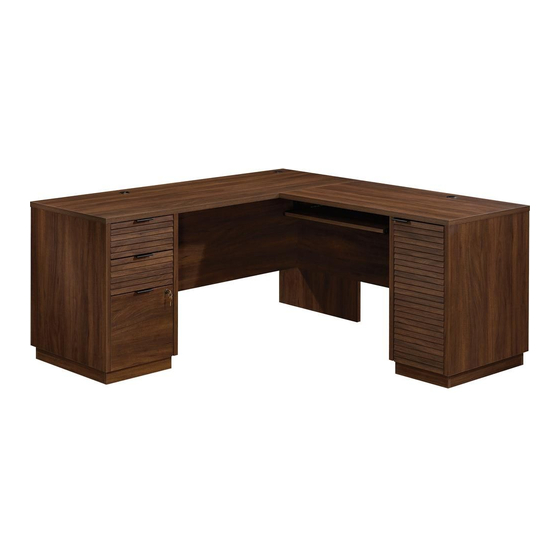
Summary of Contents for Teknik Elstree L-Shaped Desk 5426914
- Page 1 Teknik For all your newfangled gadgetry. Elstree L-Shaped Desk Model 5426914...
- Page 2 Table of Contents Assembly Tools Required Part Identification No. 2 Phillips Screwdriver Tip Shown Actual Size Hardware Identification Assembly Steps 6-52 Hammer Not actual size Tape Measure Adjustable Wrench Page 2...
- Page 3 Now you know Part Identification our ABCs. å While not all parts are labeled, some of the parts will have a label or an inked letter on the edge to help distinguish similar parts from each other. Use this part identification to help identify similar parts. RIGHT END (1) D708 DRAWER BOTTOM (3) SIDE BASE (4)
- Page 4 Hardware Identification å Screws are shown actual size. You may receive extra hardware with your unit. 40CA CABINET RIGHT - 2 40CB CABINET LEFT - 2 40CC DRAWER RIGHT - 2 40CD DRAWER LEFT - 2 (EXTENSION SET SHOWN SEPARATED) EXTENSION RAIL -2 EXTENSION SLIDE -2 40MA...
-
Page 5: Table Of Contents
Hardware Identification å Screws are shown actual size. You may receive extra hardware with your unit. Z - LOCK 76G L - LOCK BRACKET - 1 14H HINGE - 2 LOCK PACK - 1 DOOR STOP - 1 BRACKET - 1 189K PULL - 4 GROMMET CAP - 3... - Page 6 Hardware Usage Guide HOW TO USE A HIDDEN CAM & CAM DOWEL Insert the metal end of the CAM DOWEL into the HIDDEN CAM. Cam Dowel Arrow Hole Push a HIDDEN CAM into Metal end the part. The arrow in the HIDDEN CAM must point toward the hole in the edge Hidden Cam...
- Page 7 Step 1 å Assemble your unit on a carpeted floor or on the empty carton to avoid scratching your unit or the floor. å Push two SAUDER TWIST-LOCK® FASTENERS (36F) into the large holes in the MODESTY PANEL (L). å Push three HIDDEN CAMS (1F) into the MODESTY PANEL (L).
- Page 8 Step 2 å Fasten the MODESTY PANEL (L) to the LARGE UPRIGHT (G). Tighten three HIDDEN CAMS. S u r f a c i t h H I D D E N Edge with TWIST-LOCK® FASTENERS Page 8...
- Page 9 Step 5 å Fasten the MODESTY PANEL (L) and LARGE UPRIGHT (G) to the TOP (C). Tighten three HIDDEN CAMS Remember: and two SAUDER TWIST-LOCK® FASTENERS. Righty tighty. Lefty loosey. å Push a CORD CLIP (4P) into the hole in the TOP (C). å...
- Page 10 Step 6 å Push four SAUDER TWIST-LOCK® FASTENERS (36F) into the large holes in the LEFT END (B) and LEFT UPRIGHT (F). å Insert four WOOD DOWELS (15F) into the LEFT END (B) and LEFT UPRIGHT (F). Groove Page 12...
- Page 11 Step 7 å Separate the EXTENSION SLIDES (40MC) from the EXTENSION RAILS (40MA) as shown in the upper diagram below. Be prepared, the parts are greasy. å Fasten the EXTENSION RAILS (40MA) to the LEFT END (B) and LEFT UPRIGHT (F). Use four GOLD 5/16" FLAT HEAD SCREWS (3S) through holes #1 and #4.
- Page 12 Step 8 å Fasten the CABINET RIGHT (40CA) to the LEFT UPRIGHT (F) and the CABINET LEFT (40CB) to the LEFT END (B). Use eight GOLD 5/16" FLAT HEAD SCREWS (3S) through holes #1 and #4. Roller end GOLD 5/16" FLAT HEAD SCREW (8 used for the RAILS) Roller end Page 14...
- Page 13 Step 9 å Fasten the LEFT UPRIGHT (F) to the TOP (C). Tighten two SAUDER TWIST-LOCK® FASTENERS. å NOTE: Be sure the WOOD DOWELS in the LEFT UPRIGHT insert into the TOP. å Fasten the LEFT UPRIGHT (F) to the MODESTY PANEL (L). Use two BLACK 2-1/4"...
- Page 14 Step 10 å Push the LEFT BACK (S) into the groove of the LEFT UPRIGHT (F). U n fi n i s h s u r f a c Page 16...
- Page 15 Step 11 å Push four HIDDEN CAMS (1F) into the LEFT BOTTOM (R). Then, insert the metal end of a CAM DOWEL (2F) into each HIDDEN CAM. Do not tighten the HIDDEN CAMS in this step. Arrow Metal end Arrow Metal end Page 17...
- Page 16 Step 12 å Fasten the LEFT BOTTOM (R) to the LEFT UPRIGHT (F). Tighten two HIDDEN CAMS. å NOTE: Be sure the LEFT BACK (S) inserts into the groove of the LEFT BOTTOM (R). Page 18...
- Page 17 Step 13 å Fasten the LEFT END (B) to the TOP (C) and LEFT BOTTOM (R). Tighten two SAUDER TWIST-LOCK® FASTENERS. and two HIDDEN CAMS. å NOTE: Be sure the WOOD DOWELS in the LEFT END insert into the TOP. å...
- Page 18 Step 14 å Fasten four CORNER BRACKETS (31G) to the LEFT BOTTOM (R) exactly as shown. Use eight BLACK 9/16" LARGE HEAD SCREWS (1S). å NOTE: Do not tighten the screws at this time. BLACK 9/16" LARGE HEAD SCREW (8 used in this step) Page 20...
- Page 19 Step 15 å Fasten two METAL BRACKETS (4G) to two of the SIDE BASES (P). Use two BLACK 9/16" LARGE HEAD SCREWS (1S). å NOTE: Be sure the BRACKETS are even with the edges long edges of the BASES. å Fasten the SIDE BASES (P) to the BRACKETS on the LEFT BOTTOM (R).
- Page 20 Step 16 å Fasten the LEFT BASES (H) to the CORNER BRACKETS on the LEFT BOTTOM (R). Use eight BLACK 9/16" LARGE HEAD SCREWS (1S). å NOTE: Be sure the short edges of the LEFT BASES (H) are even with the surface of the SIDE BASES (P). å...
- Page 21 Step 17 å Fasten two CONNECTOR PLATES (14G) to the TOP (C). Use eight BLACK 9/16" LARGE HEAD SCREWS (1S). BLACK 9/16" LARGE HEAD SCREW (8 used in this step) Page 23...
- Page 22 Step 18 å Push two SAUDER TWIST-LOCK® FASTENERS (36F) into the large holes in the SMALL MODESTY PANEL (M). å Push two HIDDEN CAMS (1F) into the SMALL MODESTY PANEL (M). Then, insert the metal end of a CAM DOWEL (2F) into each HIDDEN CAM. Arrow Metal end Page 24...
- Page 23 Step 19 å Fasten the SMALL MODESTY (M) to the SMALL TOP (D). Tighten two SAUDER TWIST-LOCK® FASTENERS (36F). å Push a CORD CLIP (4P) into the hole in the SMALL TOP (D). å NOTE: The CORD CLIP is used to hold a cord to the SMALL TOP.
- Page 24 Step 21 å Push four SAUDER TWIST-LOCK® FASTENERS (36F) into the large holes in the RIGHT END (A) and RIGHT UPRIGHT (E). å Insert four WOOD DOWELS (15F) into the RIGHT END (A) and RIGHT UPRIGHT (E). Groove Page 27...
- Page 25 Step 22 å Fasten the RIGHT UPRIGHT (E) to the SMALL TOP (D). Tighten two SAUDER TWIST-LOCK® FASTENERS. å NOTE: Be sure the WOOD DOWELS in the RIGHT UPRIGHT insert into the TOP. å Fasten the RIGHT UPRIGHT (E) to the SMALL MODESTY PANEL (M).
- Page 26 Step 23 å Push the RIGHT BACK (T) into the groove of the RIGHT UPRIGHT (E). Page 29...
- Page 27 Step 24 å Push four HIDDEN CAMS (1F) into the RIGHT BOTTOM (J). Then, insert the metal end of a CAM DOWEL (2F) into each HIDDEN CAM. Arrow Metal end Arrow Metal end Page 30...
- Page 28 Step 25 å Fasten the RIGHT BOTTOM (J) to the RIGHT UPRIGHT (E). Tighten two HIDDEN CAMS. å NOTE: Be sure the RIGHT BACK (T) inserts into the groove of the RIGHT BOTTOM (J). Page 31...
- Page 29 Step 26 å Fasten the RIGHT END (A) to the SMALL TOP (D) and RIGHT BOTTOM (J). Tighten two SAUDER TWIST-LOCK® FASTENERS and two HIDDEN CAMS. å NOTE: Be sure the WOOD DOWELS in the RIGHT END insert into the TOP. å...
-
Page 30: Black 9/16" Large Head Screw
Step 27 å Fasten four CORNER BRACKETS (31G) to the RIGHT BOTTOM (J) exactly as shown. Use eight BLACK 9/16" Don't worry. It isn't LARGE HEAD SCREWS (1S). Rome. This can be built in a day. å NOTE: Do not tighten the screws at this time. BLACK 9/16"... - Page 31 Step 28 å Fasten two METAL BRACKETS (4G) to the SIDE BASES (P). Use two BLACK 9/16" LARGE HEAD SCREWS (1S). å NOTE: Be sure the BRACKETS are even with the long edges of the BASES. å Fasten the SIDE BASES (P) to the BRACKETS on the RIGHT BOTTOM (J).
- Page 32 Step 29 å Fasten the RIGHT BASES (O) to the CORNER BRACKETS on the RIGHT BOTTOM (J). Use eight BLACK 9/16" LARGE HEAD SCREWS (1S). å NOTE: Be sure the short edges of the RIGHT BASES (O) are even with the surface of the SIDE BASES (P). å...
-
Page 33: Silver 1-1/8" Flat Head Screw
Step 30 å You will need help from a another person in this step. å Carefully stand the two sections of your unit upright. Just breathe. It's going to be ok. å Fasten the SMALL TOP (D) to the CONNECTOR PLATE (14G) on the TOP (C). -
Page 34: Black 2-1/4" Flat Head Screw
Step 31 å Fasten two HINGES (14H) to the DOOR (V). Use four BLACK 1/2" FLAT HEAD SCREWS (11S). BLACK 1/2" FLAT HEAD SCREW (4 used in this step) Page 37... -
Page 35: Hinge
Step 32 å Before fastening the DOOR to your unit, be sure the mounting screw is against the stops as shown in the Stop right diagram. If it isn't, loosen the adjusting screw and mounting screw to slide it against the stops. Then tighten the mounting screw. - Page 36 Step 33 å Refer to the enlarged diagram to identify the parts on the HINGES. Mounting screw (depth) å The DOORS may need some adjustments. Follow the text Adjusting screw (horizontal) below to make needed adjustments. å DOOR ADJUSTMENTS: To adjust the DOORS from side to side (horizontal), turn the adjusting screw in or out.
- Page 37 Step 34 å Separate the KEYBOARD SLIDE (Z) from the KEYBOARD RAILS (X and Y) as shown in the upper view. Be prepared, the parts are greasy. å You have the option of fastening your KEYBOARD SHELF to the center, left side, or right side of your L-Desk. Shown below are the 3 options.
- Page 38 Step 35 å Fasten the KEYBOARD SLIDES (Z) to the KEYBOARD SHELF (Q). Use four SILVER 1" LARGE HEAD SCREWS (102S). Open end Open end These edges should be even. 102S SILVER 1" LARGE HEAD SCREW (4 used for the KEYBOARD SLIDES Page 41...
- Page 39 Step 36 With the palm of The tabs should insert freely your hand, tap into the slots. Gently tilt the the DRAWER DRAWER SIDES side to side BOTTOM down until the tabs slip into the slots. U n fi into the groove. n i s h s u r f a c...
- Page 40 Step 37 å Insert a SLIDE CAM (10A) into the DRAWER SIDES (D136 and D130). å Fasten the DRAWER RIGHT (40CC) to the SMALL RIGHT DRAWER SIDE (D130) and the DRAWER LEFT (40CD) to the SMALL LEFT DRAWER SIDE (D136). Use four GOLD 5/16" FLAT HEAD SCREWS (3S) through holes #1 and #4. å...
- Page 41 Step 38 With the palm of The tabs should insert freely your hand, tap into the slots. Gently tilt the the DRAWER DRAWER SIDES side to side BOTTOM down until the tabs slip into the slots. U n fi into the groove. n i s h s u r f a c...
- Page 42 Step 39 å Insert a SLIDE CAM (10A) into the LARGE DRAWER SIDES (D87 and D88). If you're doing this to help a friend, don't å Fasten the EXTENSION SLIDES (40MC) to the LARGE leave without a bite. DRAWER SIDES (D87 and D88). Use four GOLD 5/16" FLAT HEAD SCREWS (3S) through holes #1 and #4.
- Page 43 Step 40 å Push a FILE GLIDE (6B) onto the LARGE RIGHT DRAWER SIDE (D87). å Slide the FILE RODS (8B) into the FILE GLIDE (6B) on the LARGE RIGHT DRAWER SIDE (D87). å Slide another FILE GLIDE (6B) onto the other end of the FILE RODS (8B), then press this FILE GLIDE over the LARGE LEFT DRAWER SIDE (D88).
- Page 44 Step 41 å Fasten the LOCK PACK (21J) to the LOCKING DRAWER FRONT (W) in the exact order shown. å NOTE: It is important to position the CAM exactly as shown. å NOTE: Turn the KEY clockwise to lock. WASHER SCREW The prongs must press into the FILE DRAWER FRONT...
- Page 45 Step 42 å To insert the small drawers into your unit, tip the front of the drawer down and drop the rollers on the drawers behind the rollers on the unit. Lift the front of the drawers up and slide them into the unit. å...
-
Page 46: Metal Pin
Step 43 å Insert three GROMMETS (10P) and three GROMMET CAPS (1P) into the large holes in the TOP (C and D). å Insert a GROMMET (10P) into the large hole in the RIGHT UPRIGHT (E). å Push the RUBBER SLEEVES (2R) over one end of the METAL PINS (1R). - Page 47 Step 44 å To make adjustments to the drawer, loosen SCREW #4 in the SLIDES a 1/4 turn, then turn the cam clockwise or counter-clockwise. Notice how the drawer raises or lowers as you turn the cam. By adjusting the drawer this way, it will help the DRAWER FRONT line up better when closed.
- Page 48 Step 45 å If you purchased the WIRELESS CHARGER, then complete this step. å IMPORTANT: The WIRELESS CHARGING SPOT STICKER must be placed directly above the CHARGER. å First, measure in from both edges of the TOPS above your CHARGER as shown. Then, make a slight mark where the two measurements intersect.
Need help?
Do you have a question about the Elstree L-Shaped Desk 5426914 and is the answer not in the manual?
Questions and answers