Advertisement
Quick Links
Advertisement

Related Manuals for Teknik Hampstead Park 5420731


Summary of Contents for Teknik Hampstead Park 5420731
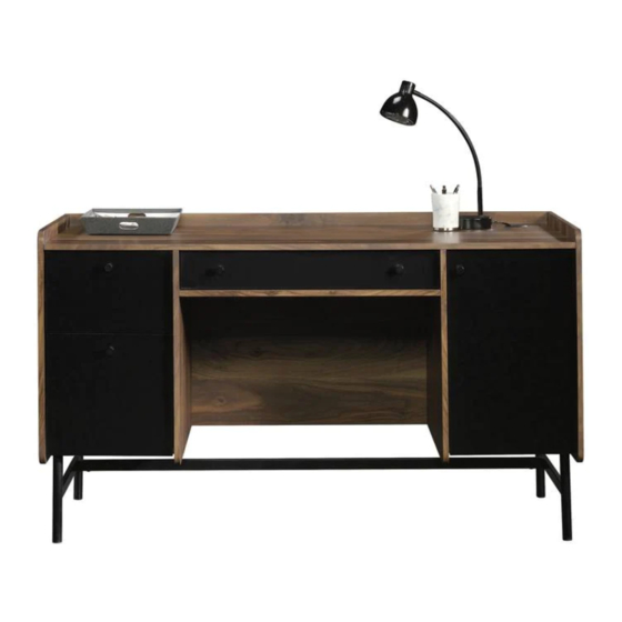
- Page 1 Teknik www.teknikoffice.co.uk Business or pleasure. Works both ways. Desk Hampstead Park Collection | Model 5420731 NOTE: THIS INSTRUCTION BOOKLET CONTAINS IMPORTANT SAFETY INFORMATION. PLEASE READ AND KEEP FOR FUTURE REFERENCE. English pg 1-38 Français pg 39-43 Español pg 44-48...
- Page 2 Table of Contents Assembly Tools Required Part Identifi cation No. 2 Phillips Screwdriver Tip Shown Actual Size Hardware Identifi cation Assembly Steps 6-38 Hammer Not actual size Français 39-43 Español 44-48 Safety 49-50 Skip the power trip. This time. Warranty Now you know Part Identifi...
- Page 3 Part Identifi cation Page 3...
- Page 4 Hardware Identifi cation å Screws are shown actual size. You may receive extra hardware with your unit. LONG EXTENSION LONG EXTENSION EXTENSION RAIL - 2 EXTENSION SLIDE - 2 RAIL - 2 SLIDE - 2 (EXTENSION SET (EXTENSION SET SHOWN SEPARATED) SHOWN SEPARATED) RIGHT CABINET LEFT CABINET...
-
Page 5: Table Of Contents
Hardware Identifi cation å Screws are shown actual size. You may receive extra hardware with your unit. 20 BLACK 1-3/8" MACHINE SCREW - 2 BLACK 1-1/2" FLAT HEAD SCREW - 19 22 BLACK 7/8" MACHINE SCREW - 5 BLACK 9/16" WAFER HEAD SCREW - 16 24 BLACK 1/2"... -
Page 6: Black 1-1/2" Flat Head Screw
Step 1 Assemble your unit on a carpeted fl oor or on the empty å carton to avoid scratching your unit or the fl oor. Some assembly Turn two ANGLED HEAD CAM SCREWS (9) into the exact å (and snacks) required. holes shown in the LEFT UPRIGHT (D). - Page 7 Step 2 Turn the LEFT UPRIGHT (D) over. å Separate the EXTENSION SLIDES (II and KK) from the EXTENSION RAILS (HH and JJ) as shown in the enlarged å diagram below. Be prepared, the parts are greasy. Fasten the EXTENSION RAILS (HH and JJ) to the LEFT UPRIGHT (D). Use six BLACK 1/2" PAN HEAD SCREWS (25). å...
-
Page 8: Black 1/2" Flat Head Screw
Step 3 Turn two ANGLED HEAD CAM SCREWS (9) into the exact holes å shown in the RIGHT UPRIGHT (C). Angled head Fasten the RIGHT CABINET RAIL (1) to the RIGHT UPRIGHT (C). å Use three BLACK 1/2" FLAT HEAD SCREWS (26). Turn the RIGHT UPRIGHT (C) over and turn four ANGLED HEAD CAM å... - Page 9 Step 4 Insert twenty-three WOOD DOWELS (12) into the å SMALL BACK (G), SHELVES (H and L), and BOTTOMS (I (23 used) and J). Page 9...
- Page 10 Step 5 Insert four HIDDEN CAMS (8) into the holes in the SHELF (H) å as shown. Fasten the SHELF (H) to the UPRIGHTS (C and D). Tighten four å HIDDEN CAMS. NOTE: Be sure the WOOD DOWELS in the SHELF insert into å...
- Page 11 Step 6 Fasten the SMALL BACK (G) to the SMALL SHELF (L). å Use two BLACK 1-1/2" FLAT HEAD SCREWS (19). NOTE: Be sure the WOOD DOWELS in the SMALL SHELF å insert into the holes in the SMALL BACK. Fasten the RIGHT BOTTOM (I) to the SMALL BACK (G).
- Page 12 Step 7 Insert six HIDDEN CAMS (8) into the exact holes shown in the å SMALL BACK (G) and BOTTOMS (I and J). Fasten the SMALL BACK (G) and BOTTOMS (I and J) to the å UPRIGHTS (C and D). Tighten six HIDDEN CAMS. NOTE: Be sure the WOOD DOWELS in the SMALL BACK and å...
-
Page 13: Black 1-1/16" Wafer Head Screw
Step 8 Turn six ANGLED HEAD CAM SCREWS (9) into the exact å holes shown in the TOP (E). Angled head Insert six WOOD DOWELS (12) into the TOP (E). å Fasten the TOP MOLDING (M) to the TOP (E). Use four å... - Page 14 Step 9 Insert six HIDDEN CAMS (8) into the UPRIGHTS (C and D) and å SMALL BACK (G) as shown. Fasten the TOP (E) to the UPRIGHTS (C and D) and SMALL å BACK (G). Tighten six HIDDEN CAMS. NOTE: Be sure the WOOD DOWELS in the UPRIGHTS and å...
- Page 15 Step 10 Fasten the EXTENSION RAILS (HH and JJ) to the LEFT å END (B). Use six BLACK 1/2" PAN HEAD SCREWS (25). NOTE: For each EXTENSION RAIL, turn a SCREW into the å Angled head hole shown in the enlarged diagram. Then, slide the inner cartridge of the EXTENSION RAIL out to fi...
- Page 16 Step 11 Turn six ANGLED HEAD CAM SCREWS (9) into the exact å holes shown in the RIGHT END (A). Angled head Fasten the HINGE BRACKETS (14) to the RIGHT END (A). å Use the screws in the HINGE BRACKETS. (6 used) Page 16...
-
Page 17: Black 9/16" Wafer Head Screw
Step 12 Insert four HIDDEN CAMS (8) into the TOP (E) and LEFT å BOTTOM (J) as shown. Fasten the LEFT END (B) to the TOP (E) and LEFT å BOTTOM (J). Tighten four HIDDEN CAMS. NOTE: Be sure the WOOD DOWELS in the TOP and LEFT å... - Page 18 Step 13 Insert six HIDDEN CAMS (8) into the TOP (E), SMALL å BACK (G), and RIGHT BOTTOM (I) as shown. Fasten the RIGHT END (A) to the TOP (E), SMALL BACK (G), å and RIGHT BOTTOM (I). Tighten six HIDDEN CAMS. BLACK 9/16"...
- Page 19 Step 14 Turn fi fteen ANGLED HEAD CAM SCREWS (9) into the å exact holes shown in the BACK (F). Angled head Insert seventeen WOOD DOWELS (12) into the exact å holes shown in the BACK (F). (15 used) (17 used) Rounded corner Page 19...
- Page 20 Step 15 NOTE: You will need someone's help in this step. å Insert fi fteen HIDDEN CAMS (8) into the LEFT END (B), UPRIGHTS (C and D), TOP (E), SHELVES (H and L), and å BOTTOMS (I and J) as shown. Fasten the BACK (F) to the LEFT END (B), UPRIGHTS (C and D) TOP (E), SHELVES (H and L), and BOTTOMS (I and J).
- Page 21 Step 16 Push the LEGS (N and O) onto the STRETCHER (P). å Side Step: Make Fasten the STRETCHER (P) to the LEGS (N and O). Use å nachos. (Optional, but four BLACK 1/2" MACHINE SCREWS (24). recommended.) BLACK 1/2" MACHINE SCREW (4 used in the step) Page 21...
- Page 22 Step 17 Fasten the LEGS (N and O) to the BOTTOMS (I and J). å Use twelve BLACK 9/16" WAFER HEAD SCREWS (23). BLACK 9/16" WAFER HEAD SCREW (12 used in this step) Page 22...
- Page 23 Step 18 Fasten the LEGS (N and O) to the BACK (F). Use two å BLACK 1-3/8" MACHINE SCREWS (20). BLACK 1-3/8" MACHINE SCREW (2 used in this step) Page 23...
- Page 24 Step 19 Turn fourteen STRAIGHT HEAD CAM SCREWS (11) into å the DRAWER FRONTS (R, X, and CC). Push fourteen SMALL HIDDEN CAMS (10) into the large å holes in the DRAWER SIDES (S, T, Y, Z, DD, and EE) and Straight head PENCIL DRAWER BRACE (W).
- Page 25 Step 20 Groove Slide the FILE DRAWER BOTTOM (GG) into the grooves å Fasten the FILE DRAWER SIDES (DD and EE) to the FILE å in the FILE DRAWER SIDES (DD and EE) and FILE DRAWER FRONT (CC). Tighten four SMALL HIDDEN CAMS. DRAWER FRONT (CC).
-
Page 26: Black 1/2" Pan Head Screw
Step 21 Fasten the KNOB (15) to the FILE DRAWER FRONT (CC). Use a BLACK 7/8" MACHINE SCREW (22). å Fasten the FRONT FILE HANGER (7) to the FILE DRAWER FRONT (CC). Use three BLACK 1/2" PAN HEAD SCREWS (25). å... - Page 27 Step 22 Push the FILE GLIDES (5) onto the FILE DRAWER SIDES (DD å and EE) as shown in the upper diagram. Push the FILE HANGER SET (6) onto the FILE GLIDES (5) as å shown in the lower diagram. Page 27...
- Page 28 Step 23 Groove Slide a DRAWER BOTTOM (BB) into the grooves in the å Fasten the DRAWER SIDES (Y and Z) to the DRAWER å DRAWER SIDES (Y and Z) and DRAWER FRONT (X). FRONT (X). Tighten four SMALL HIDDEN CAMS. BLACK 1-1/2"...
- Page 29 Step 24 Fasten the KNOB (15) to the DRAWER FRONT (X). Use a å BLACK 7/8" MACHINE SCREWS (22). Fasten the EXTENSION SLIDES (KK) to the DRAWER å SIDES (Y and Z). Use six BLACK 1/2" PAN HEAD SCREWS (25). Open end Use these holes.
- Page 30 Step 25 Groove Slide a PENCIL DRAWER BOTTOM (V) into the grooves å Fasten the PENCIL DRAWER SIDES (S and T) to the å in the PENCIL DRAWER SIDES (S and T) and PENCIL PENCIL DRAWER FRONT (R) and PENCIL DRAWER DRAWER FRONT (R).
- Page 31 Step 26 Fasten the DRAWER SLIDES (3 and 4) to the PENCIL å DRAWER SIDES (S and T). Use six BLACK 1/2" FLAT HEAD SCREWS (26). Fasten two KNOBS (15) to the PENCIL DRAWER FRONT (R). å Use two BLACK 7/8" MACHINE SCREWS (22). Roller end BLACK 1/2"...
-
Page 32: Silver 1/2" Flat Head Screw
Step 27 Fasten two HINGES (13) to the DOOR (Q). Use four å SILVER 1/2" FLAT HEAD SCREWS (27). Fasten the KNOB (15) to the DOOR (Q). Use a BLACK å 7/8" MACHINE SCREW (22). SILVER 1/2” FLAT HEAD SCREW (4 used in this step) BLACK 7/8"... - Page 33 Step 28 Carefully stand your unit upright. å Pro Tip: Lift with your To insert the pencil drawer into your unit, tip the front å legs. And, you know, of the drawer down and drop the rollers on the drawer your arms.
- Page 34 Step 29 Push the RUBBER SLEEVES over the METAL PINS (18). å Insert the METAL PINS into the hole locations of your choice in the RIGHT END (A) and RIGHT UPRIGHT (C). Set the ADJUSTABLE SHELF (K) onto the METAL PINS. (4 used) Page 34...
- Page 35 Step 30 Fasten the DOOR (Q) to the RIGHT END (A). Slide the å HINGES (13) onto the HINGE BRACKETS on the RIGHT END. Secure the DOOR with the mounting screw on the HINGE å BRACKET. See the next step for adjustments. Mounting screw Page 35...
- Page 36 Step 31 Refer to the enlarged diagram to identify the parts on å the HINGES. The DOOR may need some adjustments. Follow the å Mounting screw (depth) Adjusting screw (horizontal) text below to make needed adjustments. DOOR ADJUSTMENTS: å To adjust the DOOR from side to side (horizontal), turn the adjusting screw in or out.
- Page 37 Step 32 Fasten the BACK (F) to the RIGHT END (A). Use a BLACK å 1-1/2" FLAT HEAD SCREW (19). Insert the GROMMET (16) into the hole in the TOP (E). å BLACK 1-1/2" FLAT HEAD SCREW (1 used in this step) Page 37...
- Page 38 Step 33 Peel a sticker from the APPLIQUE CARD (17) and place it å onto each visible HIDDEN CAM and over the head of each visible SCREW. NOTE: Please read the back pages of the instruction å booklet for important safety information. This completes assembly.
Need help?
Do you have a question about the Hampstead Park 5420731 and is the answer not in the manual?
Questions and answers