
Subscribe to Our Youtube Channel
Related Manuals for Teknik Streamline L-Shaped Desk 5414417


Summary of Contents for Teknik Streamline L-Shaped Desk 5414417
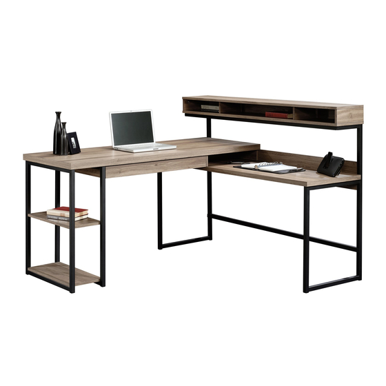
- Page 1 Teknik www.teknikoffice.co.uk For all your newfangled gadgetry. Streamline L-Shaped Desk | Model 5414417 NOTE: THIS INSTRUCTION BOOKLET CONTAINS IMPORTANT SAFETY INFORMATION. PLEASE READ AND KEEP FOR FUTURE REFERENCE.
- Page 2 Table of Contents Assembly Tools Required Part Identifi cation No. 2 Phillips Screwdriver Tip Shown Actual Size Hardware Identifi cation Assembly Steps 5-22 Hammer Not actual size Skip the power trip. Safety 29-30 This time. Warranty Part Identifi cation å While not all parts are labeled, some of the parts will have a label or an inked letter on the edge to help distinguish similar parts from each other.
- Page 3 Now you know Part Identifi cation our ABCs. Page 3...
-
Page 4: Table Of Contents
Hardware Identifi cation å Screws are shown actual size. You may receive extra hardware with your unit. (EXTENSION SET SHOWN SEPARATED) EXTENSION RAIL - 2 EXTENSION SLIDE - 2 CAM DOWEL - 19 35MA 35MC HIDDEN CAM - 19 PIVOT HINGE - 6 MAGNETIC CATCH - 1 STRIKE PLATE - 1 WASHER - 2... - Page 5 Step 1 Assemble your unit on a carpeted fl oor or on the empty å carton to avoid scratching your unit or the fl oor. Push nineteen HIDDEN CAMS (1F) into the ENDS (A and B), å UPRIGHTS (C and D), LOWER TOP (F2), DESK BACK (L), and DRAWER SIDES (R and S).
-
Page 6: Gold 5/16" Flat Head Screw
Step 2 Separate the EXTENSION SLIDES (35MC) from the å EXTENSION RAILS (35MA) as shown in the upper Remember: diagram below. Be prepared, the parts are greasy. Righty tighty. Lefty loosey. Fasten the EXTENSION RAILS (35MA) to the LOWER å END (A) and CENTER UPRIGHT (D). - Page 7 Step 3 Fasten the HUTCH ENDS (B) to the HUTCH TOP (G). å Tighten four HIDDEN CAMS. Surface with HIDDEN CAMS Caution Do not stand the unit upright without the BACK fastened. The unit may collapse. Surface with HIDDEN CAMS Long fi...
- Page 8 Step 4 Fasten the HUTCH UPRIGHTS (E) to the HUTCH BOTTOM (I). å Use four BLACK 1-7/8" FLAT HEAD SCREWS (2S). NOTE: You should start each SCREW a few turns before å completely tightening any of them. Fasten the HUTCH BOTTOM (I) to the HUTCH ENDS (B). Use å...
- Page 9 Step 5 Carefully turn your unit over onto its front edges. Lay the å Caution HUTCH BACK (N) over your unit. Do not stand the unit upright without the Make equal margins along all four edges of the HUTCH å BACK fastened.
- Page 10 Step 6 Carefully turn your unit over onto its back. å Fasten the DESK FRAMES (V) to the HUTCH BOTTOM (I). å Use four BLACK 9/16" LARGE HEAD SCREWS (1S). NOTE: The UPPER MOLDING (X) will have more holes than å...
-
Page 11: Black 3/4" Pan Head Screw
Step 7 Fasten the LOWER TOP (F2) to the LOWER BACK (M). å Tighten four HIDDEN CAMS. Fasten the LOWER TOP (F2) to the DESK FRAMES (V). å Use six BLACK 3/4" PAN HEAD SCREWS (85S). Maximum Arrow i t h 210 degrees f a c S u r... - Page 12 Step 8 Fasten the UPRIGHT (C) to the TOP (H2). Tighten two å HIDDEN CAMS. Don't worry. It isn't Rome. This can be built Push the MAGNETIC CATCH (2I) into the hole on å in a day. the TOP (H2). Large hole These holes should be here.
- Page 13 Step 9 Insert four METAL PINS (1R) into the DIVIDER (U). å Maximum Arrow Insert the METAL PINS (1R) in one end of the DIVIDER (U) å 210 degrees into the holes in the UPRIGHT (C). Fasten the CENTER UPRIGHT (D) to the TOP (H2). å...
-
Page 14: Hidden Cam
Step 10 Fasten the LOWER END (A) and DESK BACK (L) to the å TOP (H2). Tighten fi ve HIDDEN CAMS. Maximum Arrow 210 degrees Minimum 190 degrees Surface with HIDDEN CAMS Finished edge i t h f a c S u r D E N H I D... - Page 15 Step 11 Fasten the BOTTOM (K) to a RETURN FRAME (W). Use three å BLACK 9/16" LARGE HEAD SCREWS (1S). 1st - Insert a PIVOT HINGE (15H) into the lower center hole in å the RETURN FRAME (W). Fasten the SHELF (J) to the PIVOT HINGE in the RETURN FRAME.
- Page 16 Step 12 Fasten the other RETURN FRAME (W) to the BOTTOM (K). å Use three BLACK 9/16" LARGE HEAD SCREWS (1S). 1st - Insert a PIVOT HINGE (15H) into the lower center hole in å the RETURN FRAME (W). Fasten the SHELF (J) to the PIVOT HINGE in the RETURN FRAME.
- Page 17 Step 13 Fasten the RETURN FRAMES (W) to the TOP (H2). Use å six BLACK 3/4" PAN HEAD SCREWS (85S). BLACK 3/4" PAN HEAD SCREW (6 used in this step) Page 17...
-
Page 18: Strike Plate
Step 14 Fasten a PIVOT HINGE (15H) to the FLIP DOWN DOOR (O). Use å a BLACK 9/16" LARGE HEAD SCREW (1S). Fasten the STRIKE PLATE (6I) to the FLIP DOWN DOOR (O). Use å a BLACK 1/2" FLAT HEAD SCREW (11S). NOTE: The surface of the STRIKE PLATE with "SAUDER"... -
Page 19: Black 1-7/8" Flat Head Screw
Step 15 Carefully stand your unit upright. å Pro Tip: Lift with your Fasten the UPRIGHTS (C and D) to the LOWER TOP (F2). Use å legs. And, you know, four BLACK 1-7/8" FLAT HEAD SCREWS (2S). your arms. Fasten the LOWER MOLDING (Y) to the DESK FRAMES (V). Use å... - Page 20 Step 16 Fasten the PULL (21K) to the DRAWER BOTTOM (T). Use å two BLACK 1/2" FLAT HEAD SCREWS (11S). Fasten the DRAWER SIDES (R and S) to the å DRAWER BOTTOM (T). Use four BLACK 1-7/8" FLAT HEAD SCREWS (2S). Fasten the DRAWER BACK (Q) to the å...
- Page 21 Step 17 Fasten the DRAWER FRONT (P) to the DRAWER å SIDES (R and S). Tighten two HIDDEN CAMS. Maximum Arrow 210 degrees Fasten the EXTENSION SLIDES (35MC) to the DRAWER å SIDES (R and S). Use four GOLD 5/16" FLAT HEAD Minimum SCREWS (3S) through the center slotted holes and #3.
- Page 22 Step 18 To insert the drawer into your unit, line up the EXTENSION SLIDES on the drawer with the å EXTENSION RAILS on the unit and push the drawer into the unit until the drawer is fully inserted. The drawer will push in hard until it is all the way in, then it will slide in and out easier. NOTE: Please read the back pages of the instruction booklet for important safety information.
- Page 23 WARNING Please use your furniture correctly and safely. Improper use can cause safety hazards, or damage to your furniture or household items. Carefully read the following chart. Look out for: What can happen: How to avoid the problem: • Overloaded shelves and drawers. •...
Need help?
Do you have a question about the Streamline L-Shaped Desk 5414417 and is the answer not in the manual?
Questions and answers