
Related Manuals for Teknik Lateral Filer 5421114


Summary of Contents for Teknik Lateral Filer 5421114
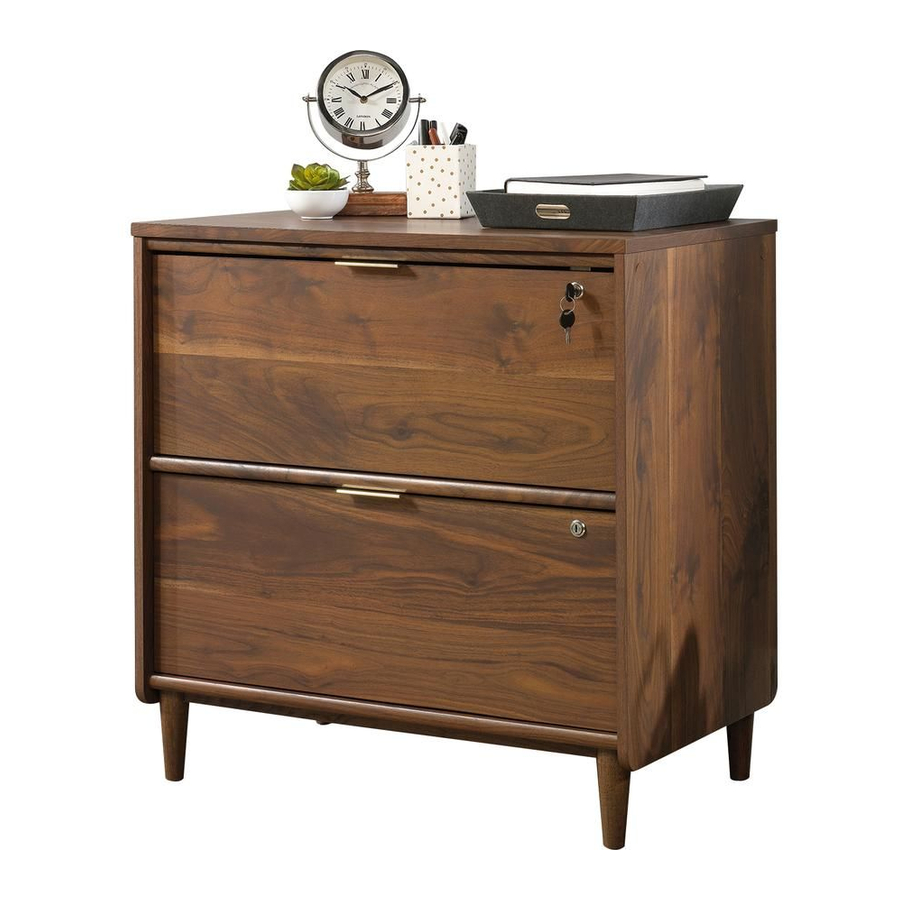
- Page 1 Teknik www.teknikoffice.co.uk Congratulations. You are now an adult. Lateral Filer Clifton Place Collection | Model 5421114 NOTE: THIS INSTRUCTION BOOKLET CONTAINS IMPORTANT SAFETY INFORMATION. PLEASE READ AND KEEP FOR FUTURE REFERENCE.
- Page 2 Table of Contents Assembly Tools Required Part Identifi cation No. 2 Phillips Screwdriver Tip Shown Actual Size Hardware Identifi cation Assembly Steps 5-24 Skip the power trip. This time. Page 2...
- Page 3 Now you know Part Identifi cation our ABCs. å While not all parts are labeled, some of the parts will have a label or an inked letter on the edge to help distinguish similar parts from each other. Use this part identifi cation to help identify similar parts. RIGHT END (1) BOTTOM (1) DRAWER FRONT (2)
- Page 4 Hardware Identifi cation å Screws are shown actual size. You may receive extra hardware with your unit. ANGLED HEAD LARGE HIDDEN EXTENSION SLIDE - 4 EXTENSION RAIL - 4 CAM - 20 CAM SCREW - 20 (EXTENSION SET SHOWN SEPARATED) Angled head STRAIGHT HEAD LONG WOOD...
- Page 5 Step 1 Assemble your unit on a carpeted fl oor or on the empty å carton to avoid scratching your unit or the fl oor. NOTE: If you are attaching the 421116 Hutch to your unit, å build the Hutch fi rst. Push twenty HIDDEN CAMS (1) into the å...
- Page 6 Step 2 Peel an applique from the LARGE APPLIQUE CARD (20) å and stick one on each large hole in the BOTTOM (H). Flip the BOTTOM (H) over. å Turn and tighten four FEET (P) into the threaded holes in å...
- Page 7 Step Step 3 Insert four SHORT WOODEN DOWELS (7) into the å BOTTOM (H). Fasten the BOTTOM MOLDINGS (I) to the BOTTOM (H). å Use six BLACK 1-1/8" FLAT HEAD SCREWS (22). NOTE: Be sure the SHORT WOODEN DOWELS insert å...
- Page 8 Step Step 4 Turn twenty ANGLED HEAD CAM SCREWS (2) into the å ENDS (A and B) and TOP (C). Angled head (20 used) Remember: Righty tighty. Lefty loosey. Page 8...
- Page 9 Step Step 5 Separate the EXTENSION SLIDES (R) from the EXTENSION RAILS (Q) as å shown in the enlarged diagram below. Be prepared, the parts are greasy. Fasten the EXTENSION RAILS (Q) to the ENDS (A and B). Use twelve å...
- Page 10 Step Step 6 Gather two LOCK BRACKETS from the LOCK PACK (15). å Fasten the LOCK BRACKETS to the BRACE (F) and TOP å MOLDING (D) as shown. Use four SILVER 1/2" FLAT HEAD SCREWS (24). SILVER 1/2" FLAT HEAD SCREW (4 used in this step) LOCK BRACKET from LOCK PACK (15)
- Page 11 Step Step 7 Turn and tighten four HOOKS (18) into the BACKS (E and G). å After the HOOKS are tight, turn them counter clockwise å a half revolution or 180 degrees. It is important that these HOOKS are in this position for optimal performance of the ANTI-TIP KIT.
- Page 12 Step Step 8 Insert three WOOD DOWELS (6) into the RIGHT END (A). å Fasten the BACKS (E and G) to the RIGHT END (A). å Tighten four HIDDEN CAMS. NOTE: Be sure the WOOD DOWELS in the RIGHT END å...
- Page 13 Step Step 9 Insert two WOOD DOWELS (6) into the RIGHT END (A) å and two WOOD DOWELS (6) into the LOWER BACK (G). Fasten the BOTTOM (H) to the RIGHT END (A) as shown å in the upper diagram. Tighten two HIDDEN CAMS. NOTE: Be sure the WOOD DOWELS in the RIGHT END å...
- Page 14 Step Step 10 Insert fi ve WOOD DOWELS (6) into the LEFT END (B). å Fasten the LEFT END (B) to the UPPER BACK (E), å BRACE (F), LOWER BACK (G) and BOTTOM (H). Tighten seven HIDDEN CAMS. NOTE: Be sure the WOOD DOWELS in the LEFT END å...
- Page 15 Step Step 11 Insert two SHORT WOODEN DOWELS (7) into the TOP (C). å Now might be a Fasten the TOP MOLDING (D) to the TOP (C). Use three å good time to refresh BLACK 1-1/8" FLAT HEAD SCREWS (22). your drink.
- Page 16 Step 12 Turn twelve STRAIGHT HEAD CAM SCREWS (4) into the å DRAWER FRONTS (O). Push twelve SMALL HIDDEN CAMS (3) into the large å holes in the DRAWER SIDES (J and L) and DRAWER Straight head BRACE (N). (12 used) Arrow Hole Arrow...
- Page 17 Step 13 Surface with HIDDEN CAMS f a c s u r n i s h U n fi Groove Fasten a LEFT DRAWER SIDE (J), a RIGHT DRAWER å Slide a DRAWER BOTTOM (M) into the grooves å SIDE (L) and a DRAWER BRACE (N) to a DRAWER in the DRAWER SIDES (J and L) and DRAWER FRONT (O).
- Page 18 Step 14 Fasten the EXTENSION SLIDES (R) to the DRAWER å SIDES (J and L). Use six BLACK 1/2" PAN HEAD SCREWS (25). Repeat this step for the other drawer. å Open end Use these holes. Open end BLACK 1/2" PAN HEAD SCREW (12 used in this step) Open end Page 18...
- Page 19 Step 15 Fasten a Lock from the LOCK PACK (15) to a DRAWER å FRONT (O). Use four SILVER 5/8" FLAT HEAD SCREWS (23). Fasten a PULL (8) to the DRAWER FRONT (O). Use two å SILVER 1/2" FLAT HEAD SCREWS (24). Fasten the NOTCHED FILE GLIDE (13) to the DRAWER å...
- Page 20 Step 16 Push two SHORT FILE GLIDES (11) onto the top edges of å the DRAWER SIDES (J and L). If you're doing this to help a friend, don't Push the LONG FILE GLIDE (12) onto the top edge of the å...
- Page 21 Step 17 Carefully stand your unit upright. å Loop the straps from the ANTI TIP KIT (17) through the å HOOKS in the BACKS (E and G) as shown below. Then insert a drawer into the lower EXTENSION RAILS å strap of your unit by lining up the EXTENSION SLIDES on the machine...
- Page 22 Step 18 Insert the upper drawer into the upper EXTENSION RAILS å of your unit by lining up the EXTENSION SLIDES on the drawer with the EXTENSION RAILS on the unit. Push the strap drawer into the unit until the drawer is fully inserted. The drawer will push in hard until it is all the way in, then it will machine slide in and out easier.
- Page 23 Step Step 19 Insert six WOOD DOWELS (6) into the ENDS (A and B) å and UPPER BACK (E). Fasten the TOP (C) to the ENDS (A and B) and UPPER å BACK (E). Tighten six HIDDEN CAMS. NOTE: Be sure the WOOD DOWELS in the ENDS and å...
- Page 24 Step 20 Push a GROMMET WITH CAP (9) into the hole in å the TOP. (C). Peel an applique from the SMALL APPLIQUE CARD (19) å and stick them on the visible HIDDEN CAMS. NOTE: To raise a corner of the unit, turn the ADJUSTABLE å...
- Page 25 CAUTION Please use your furniture correctly and safely. Improper use can cause safety hazards, or damage to your furniture or household items. Carefully read the following chart. Look out for: What can happen: How to avoid the problem: • Overloaded drawers. •...
Need help?
Do you have a question about the Lateral Filer 5421114 and is the answer not in the manual?
Questions and answers