
Related Manuals for ADLINK Technology VPX3001 Series


Summary of Contents for ADLINK Technology VPX3001 Series
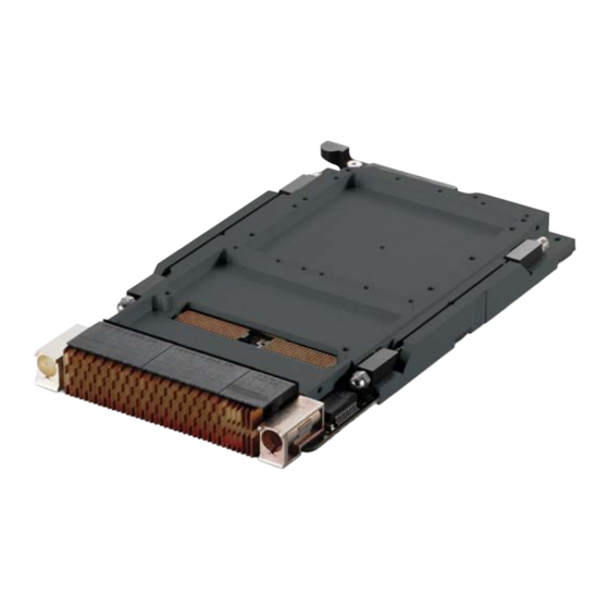
- Page 1 VPX3001 Series Performance Rugged Conduction Cooled 3U VPX 3rd Gen Intel® Core™ i7 Processor Blade Manual Rev.: Revision Date: June 3, 2019 Part No: 50-15102-2000 Leading EDGE COMPUTING...
- Page 2 Leading EDGE COMPUTING Revision History Revision Release Date Description of Change(s) 2019/06/03 Initial release Revision History...
-
Page 3: Preface
VPX3001 Preface Copyright © 2019 ADLINK Technology Inc. This document contains proprietary information protected by copy- right. All rights are reserved. No part of this manual may be repro- duced by any mechanical, electronic, or other means in any form without prior written permission of the manufacturer. - Page 4 Leading EDGE COMPUTING California Proposition 65 Warning WARNING: This product can expose you to chemicals including acrylamide, arsenic, benzene, cadmium, Tris(1,3-dichloro-2-propyl)phosphate (TDCPP), 1,4-Diox- ane, formaldehyde, lead, DEHP, styrene, DINP, BBP, PVC, and vinyl materials, which are known to the State of California to cause cancer, and acrylamide, benzene, cadmium, lead, mercury, phthalates, toluene, DEHP, DIDP, DnHP, DBP, BBP, PVC, and vinyl materials, which are known to the State of California to cause...
-
Page 5: Table Of Contents
VPX3001 Table of Contents Revision History..............ii Preface ..................iii List of Figures ............... vii List of Tables................ix 1 Introduction ................ 1 Overview................1 Features................2 Block Diagrams..............3 Model Number Decoder - Processor Blade ......5 Package Contents ............... 6 2 Specifications .............. - Page 6 Leading EDGE COMPUTING 5 VPX-R3001 RTM ..............25 VPX-R3001 Specifications..........25 VPX-R3001 RTM Board Layout......... 26 VPX-R3001 RTM Connector Pin Assignments....27 6 Getting Started ..............37 Installing the VPX3001 to the Chassis....... 37 Installing the VPX-R3001 to the Chassis ......37 Driver Installation ...............
-
Page 7: List Of Figures
VPX3001 List of Figures Figure 1-1: VPX3001 Functional Block Diagram........ 3 Figure 1-2: VPX-R3001 RTM Functional Block Diagram ....4 Figure 4-1: VPX3001 Board Layout ..........17 Figure 4-2: VPX3001 Mechanical Dimensions......... 18 Figure 4-3: VPX3001 Front View ............. 18 Figure 5-1: VPX-R3001 RTM Board Layout........ - Page 8 Leading EDGE COMPUTING This page intentionally left blank. viii List of Figures...
-
Page 9: List Of Tables
VPX3001 List of Tables Table 2-1: VPX3001 Blade Specifications ........7 Table 2-2: VPX-R3001 RTM Specifications........9 List of Tables... - Page 10 Leading EDGE COMPUTING This page intentionally left blank. List of Tables...
-
Page 11: Introduction
VPX3001 Introduction 1.1 Overview The VPX3001 Series is a 3U VPX processor blade featuring the 3rd Generation Intel® Core™ i7 processor with Mobile Intel® QM77 Express Chipset. The VPX3001 provides up to 8GB DDR3-1066/1333 dual channel ECC memory soldered onboard, one PCI Express x8 XMC.3 site with VITA 46.9 rear IO, and... -
Page 12: Features
Leading EDGE COMPUTING 1.2 Features 3U VPX VITA 46, OpenVPX VITA 65, VPX REDI 48 4HP (0.8") rugged conduction cooled 3U VPX blade with conformal coating Intel® 3rd generation Core™ i7-3612QE Processor (4 cores, 6M cache, 2.1 GHz, 35W TDP) Dual channel DDR3-1333/1666 SDRAM with ECC soldered onboard, up to 8GB Intel®... -
Page 13: Block Diagrams
VPX3001 1.3 Block Diagrams PCIe 2.0 x8 X24s+x8d+x12d DDR3-1600 Quad-core 3rd Gen 1x PCIe x8 PCIe 2.0 x8 Intel® Core™ i7 DDR3-1600 PCIe Switch PEX8619 2x PCIe x4 BASE-T [opt. BASE-BX] 1000BASE-T 1x SATA 3Gb/s PCIe 2.0 x4 Intel® QM77 32GB Flash 1000BASE-T Intel 82580EB... -
Page 14: Figure 1-2: Vpx-R3001 Rtm Functional Block Diagram
Leading EDGE COMPUTING VS1(DC12V), 8A/Slot VS2(DC3V), 8A/Slot VS3(DC5V), 16A/Slot DC3V_AUX, 1A/Slot DC12V_AUX, 1A/Slot DC-12V_AUX, 1A/Slot VBAT NVMRO, SYSRESET# JTAG SMBus PCIe x8 PCIe x8 1000BASE-BX 1000BASE-BX x2 ports, SERDES (optional) 1000BASE-T 1000BASE-T x2 ports SATA SATA x1 port USB 2.0 USB 2.0 x2 port RS232 RS232 x1 port... -
Page 15: Model Number Decoder - Processor Blade
VPX3001 Model Number Decoder - Processor Blade VPX3001/3612/M8/S32-R1 (B) (C) (A) CPU Code 3612 = Quad-Core Intel® i7-3612QE processor 3555 = Dual-Core Intel® i7-2655LE processor (B) Memory Size Code M8 = Onboard 8GB DDR3-1333/1600 memory M16 = Onboard 16GB DDR3-1333/1600 memory (C) SATA NAND Flash Size Code S32 = Onboard 32GB (D) Ruggedized Level Code... -
Page 16: Package Contents
Leading EDGE COMPUTING 1.5 Package Contents The VPX3001 is packaged with the following components. If any of the items on the contents list are missing or damaged, retain the shipping carton and packing material and contact the dealer for inspection. Please obtain authorization before returning any prod- uct to ADLINK. -
Page 17: Specifications
VPX3001 Specifications 2.1 VPX3001 Blade Specifications VITA Standards • VITA 46.0 VPX Base Standard • VITA 46.4 PCI Express on VPX Fabric Connector • VITA 46.6 Gigabit Ethernet Control Plane on VPX • VITA 46.9 PMC/XMC/Ethernet Signal Mapping to 3U/6U •... - Page 18 Leading EDGE COMPUTING • One PCIe 2.0 x8 conduction cooled XMC.3 site • XMC I/O connector compliant to VITA 46.9, X24s+X8d+X12d Front Panel I/O • Reset button • Power LED Storage • Onboard SATA NAND flash on SATA 3 Gb/s, up to 32GB •...
-
Page 19: Vpx-R3001 Rtm Specifications
VPX3001 2.2 VPX-R3001 RTM Specifications VITA Standards • VITA 46.10 Rear Transition Module on VPX Mechanical • 100mm x 80mm Faceplate I/O • VGA port • 2x 1000BASE-BX connectors Onboard • 2x 1000BASE-T vertical connectors Interfaces • 1x SATA 6Gb/s ports •... -
Page 20: Power Consumption
Consumption This section provides information on the power consumption of the VPX3001 Series when using Intel® Core i7 processors with Dual Channel 8GB DDR3-1333 soldered memory and soldered onboard 32GB SATA SSD. The VPX3001 is powered by 12V, 5V and 3.3V. -
Page 21: Functional Description
VPX3001 Functional Description The following sections describe the VPX3001 features and functions. 3.1 Processors The 3rd Generation Intel® Core™ i7 Processor is the next genera- tion of 64-bit, multi-core mobile processors built on 22-nanometer process technology. Based on a new micro-architecture, the pro- cessor is designed for a two-chip platform. - Page 22 Leading EDGE COMPUTING Supported Technologies Intel® Virtualization Technology for Directed I/O (Intel® VT-d) Intel® Virtualization Technology (Intel® VT-x) Intel® vPro Technology (Intel® VT) Intel® Trusted Execution Technology (Intel® TXT) Intel® Hyper-Threading Technology Intel® 64 Architecture Intel® Turbo Boost Technology 2.0 AES New Instructions Intel®...
-
Page 23: Chipset
VPX3001 3.2 Chipset The VPX3001 incorporates the Mobile Intel® QM77 Express Chip- set (Intel® BD82QM77 PCH). Mobile Intel® QM77 Express Chipset PCI Express Base Specification, Revision 2.0 support for up to eight ports with transfer rate up to 5 GT/s Supports dual display ACPI Power Management Logic Support, Revision 4.0a Enhanced DMA controller, interrupt controller, and timer... -
Page 24: Intel® Turbo Boost Technology
Leading EDGE COMPUTING 3.3 Intel® Turbo Boost Technology Intel Turbo Boost Technology is a feature that allows the processor to opportunistically and automatically run faster than its rated operating core and/or render clock frequency when there is suffi- cient power headroom, and the product is within specified temper- ature and current limits. -
Page 25: Xmc Site
VPX3001 3.5 XMC Site The VPX3001 Series supports one XMC site for rear I/O expan- sion. The XMC site provides a x8 PCI Express 2.0 lane. Jn6 rear XMC I/O connector is compliant to VITA 46.9, X8d+X12d. 3.6 Real Time Clock The Intel®... - Page 26 Leading EDGE COMPUTING This page intentionally left blank. Functional Description...
-
Page 27: Vpx3001 Board Interfaces
VPX3001 VPX3001 Board Interfaces 4.1 VPX3001 Board Layout PCIe Switch Memory XMC SSD Intel Core Processor 32GB SATA NAND flash Intel QM77 PCH XMC connectors PCIe Switch Pericom PEX8619 Memory DDR3 memory chips Bridge P0-2 Intel 82580EB VPX connectors Ethernet Controller Figure 4-1: VPX3001 Board Layout VPX3001 Board Interfaces... -
Page 28: Vpx3001 Mechanical Drawing
Leading EDGE COMPUTING 4.2 VPX3001 Mechanical Drawing Dimensions in mm Figure 4-2: VPX3001 Mechanical Dimensions PWR System LED Reset Reset Figure 4-3: VPX3001 Front View Power LED Color Condition Indication System is off Green Power System is on VPX3001 Board Interfaces... - Page 29 VPX3001 System Reset Resets the system. RTC Reset Resets BIOS settings to factory default settings. VPX3001 Board Interfaces...
-
Page 30: Vpx3001 Connector Pin Assignments
Leading EDGE COMPUTING 4.3 VPX3001 Connector Pin Assignments XMC Connectors JN1 Connector RXP0 RXN0 +3.3V RXP1 RXN1 VPWR TRST# MRSTI# RXP2 RXN2 +3.3V RXP3 RXN3 VPWR MRSTO# RXP4 RXN4 +3.3V RXP5 RXN5 VPWR +12V RXP6 RXN6 +3.3V RXP7 RXN7 VPWR -12V_AUX TXP0 TXN0... - Page 31 VPX3001 JN2 Connector P2-E7 P2-D7 P2-B7 P2-A7 P2-F8 P2-E8 P2-C8 P2-B8 P2-E11 P2-D11 P2-B11 P2-A11 P2-F12 P2-E12 P2-C12 P2-B12 P2-E1 P2-B1 P2-E13 P2-D13 P2-D1 P2-B13 P2-A13 P2-A1 P2-F2 P2-C2 P2-E9 P2-D9 P2-E2 P2-B9 P2-A9 P2-B2 P2-E3 P2-B3 P2-F10 P2-E10 P2-D3 P2-C10 P2-B10 P2-A3...
- Page 32 Leading EDGE COMPUTING VPX Connectors P0 Connector +12V +12V +12V None +3.3V +3.3V +3.3V +12V +12V +12V None +3.3V +3.3V +3.3V None I2C_CLK I2C_DAT +12V_AUX SYSRESET +3.3V_AUX SM0_CLK SM1_DATA +12V_AUX TRST REF_CLK- REF_CLK+ P1 Connector L0-TX- L0-TX+ L0-RX- L0-RX+ L1-TX- L1-TX+ L1-RX- L1-RX+...
- Page 33 VPX3001 P2 Connector VGA0_RED J16-C8 J16-C9 J16-F8 J16-F9 J16-C10 J16-C11 J16-F10 J16-F11 VGA0_GREEN J16-C12 J16-C13 J16-F12 J16-F13 J16-C14 J16-C15 J16-F14 J16-F15 VGA0_BLUE J16-C16 J16-C17 J16-F16 J16-F17 J16-C18 J16-C19 AGND J16-F18 J16-F19 AGND VGA0_VSYNC J16-A1 J16-B1 J16-D1 J16-E1 J16-A3 J16-B3 J16-D3 J16-E3 VGA0_HSYNC J16-A11 J16-B11...
- Page 34 Leading EDGE COMPUTING This page intentionally left blank. VPX3001 Board Interfaces...
-
Page 35: Vpx-R3001 Rtm
VPX3001 VPX-R3001 RTM 5.1 VPX-R3001 Specifications Form Factor • VPX RTM IO Ports • Two USB 2.0 ports on board. • Two RJ-45 LAN ports.(two ports SERDES optional) • One SATA 6Gb/s ports • One RS-232 port on board • One VPX JTAG port. •... -
Page 36: Vpx-R3001 Rtm Board Layout
Leading EDGE COMPUTING 5.2 VPX-R3001 RTM Board Layout SMBUS SATA LED1 LED6 JTAG USB 2.0 RS-232 GPIO 1000BASE-BX 1000BASE-BX 1000BASE-T 1000BASE-T SMBUS VPX SMBus pin header SATA SATA connector (7-pin) VGA connector (DB-15) 1000BASE-BX 1000BASE-BX Connector JTAG VPX JTAG Connector USB 2.0 USB 2.0 pin header GPIO... -
Page 37: Vpx-R3001 Rtm Connector Pin Assignments
VPX3001 5.3 VPX-R3001 RTM Connector Pin Assignments Rear I/O Connectors VGA Connector Signal Name Pin # Pin # Signal Name Green Blue N.C. +5V. N.C. CRTDATA HSYNC VSYNC CRTCLK BX Connectors Pin # GbE Signal GND1 TP2_R TN2_R GND2 RN2_R RP2_R GND3 VPX-R3001 RTM... - Page 38 Leading EDGE COMPUTING Onboard Connectors Gigabit Ethernet Connectors (RJ-45, (CN9/10) Pin # Signal MX0+ MX0- MX1+ MX2+ MX2- MX1- MX3+ MX3- RS-232 Header (CN20) Pin # Signal N.C. P1_SOUT P1_SIN N.C. N.C. P2_SOUT P2_SIN N.C. VPX-R3001 RTM...
- Page 39 VPX3001 VPX JTAG Header (CN22) Pin # Signal P0_TCK P0_TDO P0_TMS P3V3_PSU P3V3_PSU P0_TRST P0_TDI USB 2.0 Connector (CN30) Pin # Signal P5V_USB P5V_USB USB_N6_L USB_N0_L USB_P6_L USB_P0_L VPX-R3001 RTM...
- Page 40 Leading EDGE COMPUTING SATA Connector (CN32/36) Pin # Signal VPX SMBus 2 & 3 (CN95) Pin # Signal IPMB_DAT IPMB_CLK P5V_PSU P5V_PSU VPX-R3001 RTM...
- Page 41 VPX3001 GPIO Connector (JP11) Pin # Signal SMBUS_GPIO0 SMBUS_GPIO1 SMBUS_GPIO2 SMBUS_GPIO3 SMBUS_GPIO4 SMBUS_GPIO5 GPIO LEDs LED # Signal LED1 GPIO0 LED2 GPIO1 LED3 GPIO2 LED4 GPIO3 LED5 GPIO4 LED6 GPIO5 VPX-R3001 RTM...
- Page 42 Leading EDGE COMPUTING XMC Connector (CN83) JN6-A1 JN6-B1 JN6-D1 JN6-E1 JN6-A3 JN6-B3 JN6-D3 JN6-E3 JN6-A5 JN6-B5 JN6-D5 JN6-E5 JN6-A7 JN6-B7 JN6-D7 JN6-E7 JN6-C8 JN6-F8 JN6-A9 JN6-B9 JN6-C9 JN6-D9 JN6-E9 JN6-F9 JN6-C10 JN6-F10 JN6-A11 JN6-B11 JN6-C11 JN6-D11 JN6-E11 JN6-F11 JN6-C12 JN6-F12 JN6-A13 JN6-B13 JN6-C13...
- Page 43 VPX3001 RTM VPX Connectors RP0 Connector P12V P12V P12V P3V3 P3V3 P3V3 P3V3 I2C_CLK I2C_DAT IPMB_CLK IPMB_DAT TRST VPX-R3001 RTM...
- Page 44 Leading EDGE COMPUTING RP1 Connector COM1_TX SATA_TX0- SATA_TX0+ SATA_RX0- SATA_RX0+ USB1- USB1+ USB0- USB0+ COM1_RX GPIO1 GPIO0 P5V_USB1 P5V_USB0 GPIO5 GPIO4 GPIO3 GPIO2 COM2_TX MDI1_B- MDI1_B+ MDI1_A- MDI1_A+ MDI1_D- MDI1_D+ MDI1_C- MDI1_C+ MDI2_B-/ MDI2_B+/ MDI2_A-/ MDI2_A+/ MASK_RESET-L BX1_T- BX1_T+ BX1_R- BX1_R+ MDI2_D-/ MDI2_D+/...
- Page 45 VPX3001 RP2 Connector VGA_HSYNC JN6-A11 JN6-B11 JN6-D11 JN6-E11 JN6-A13 JN6-B13 JN6-D13 JN6-E13 COM2_RX JN6-A5 JN6-B5 JN6-D5 JN6-E5 JN6-A7 JN6-B7 JN6-D7 JN6-E7 DDC_CLK JN6-A9 JN6-B9 JN6-D9 JN6-E9 JN6-A15 JN6-B15 JN6-D15 JN6-E15 DDC_DATA JN6-A11 JN6-B11 JN6-D11 JN6-E11 JN6-A19 JN6-B19 JN6-D19 JN6-E19 VPX-R3001 RTM...
- Page 46 Leading EDGE COMPUTING This page intentionally left blank. VPX-R3001 RTM...
-
Page 47: Getting Started
RTMs. Refer to previous sections for peripheral connectivity of all I/O ports on the RTM. When installing the VPX3001 Series and related RTMs, make sure the RTM is the correct matching model. Getting Started... -
Page 48: Driver Installation
Leading EDGE COMPUTING 6.3 Driver Installation The VPX3001 drivers are available from the ADLINK website (www.adlinktech.com). ADLINK provides validated drivers for Windows 7. Follow the steps below to install the drivers for Windows 7 64-bit. 1. Install the Windows operating system before installing any driver. -
Page 49: Utilities
VPX3001 Utilities 7.1 Watchdog Timer This section describes the operation of the VPX3000’s watchdog timer (WDT). The primary function of the WDT is to monitor the VPX3000's operation and to reset the system if a software applica- tion fails to function as programmed. The following WDT functions may be controlled using a software application: enabling and disabling set and get current configuration... - Page 50 Leading EDGE COMPUTING Reset Watchdog Timer This command is used to reload the WDT. Action Byte Value Description Request NetFn/LUN Defined command Response 0 Complete Code 00h means OK Set Watchdog Timer: This command is used to set the parameters of the WDT. Action Byte Value Description...
- Page 51 VPX3001 Action Byte Value Description 1h~ffh ( ‘1h’ based.) Pre-timeout interval in Request seconds. [7] - reserved Timer Use Expiration flags [6] - reserved clear [5] - OEM [4] - SMS/OS [3] - OS Load [2] - BIOS/POST [1] - BIOS FRB2 [0] - reserved 0b = leave alone 1b = clear timer use expiration bit...
- Page 52 Leading EDGE COMPUTING Action Byte Value Description Response 2 [7] - reserved Timer Actions [6:4] - pre-timeout interrupt 000b = none 001b = SMI (optional) 010b = NMI / Diagnostic Interrupt (optional) 011b = Messaging Interrupt 100b,111b = reserved [3] - reserved [2:0] - timeout action 000b = no action 001b = Hard Reset...
- Page 53 VPX3001 Example of WDT Process The sample program written in C shown below offers an interac- tive way to test the Watchdog Timer under DOS. Configure WDT Parameters 0x40 : Don't stop timer. 0x01 : Hard Reset. 0x01 : Pre-timeout interval in 1 second. 0x08 : Timer Use Expiration flags clear by OS Load.
- Page 54 Leading EDGE COMPUTING This page intentionally left blank. Utilities...
-
Page 55: Bios Setup
VPX3001 BIOS Setup The following chapter describes basic navigation for the AMIBIOS®8 BIOS setup utility. 8.1 Starting the BIOS To enter the setup screen, follow these steps: 1. Power on the motherboard 2. Press the < Delete > key on your keyboard when you see the ADLINK Logo (Quiet Boot enabled) or the text prompt: <... - Page 56 Leading EDGE COMPUTING Setup Menu The main BIOS setup menu is the first screen that you can navi- gate. Each main BIOS setup menu option is described in this user’s guide. The Main BIOS setup menu screen has two main frames. The left frame displays all the options that can be configured.
- Page 57 VPX3001 Navigation The BIOS setup/utility uses a key-based navigation system called hot keys. Most of the BIOS setup utility hot keys can be used at any time during the setup navigation process. These keys include < F1 >, < F4 >, < Enter >, < ESC >, < Arrow > keys, and so on. There is a hot key legend located in the right frame on most setup screens.
- Page 58 Leading EDGE COMPUTING Hotkey Descriptions Enter The < Enter > key allows you to display or change the setup option listed for a particular setup item. The < Enter > key can also allow you to display the setup sub-screens. The <...
- Page 59 VPX3001 conflicting settings. The < F4 > key allows you to save any changes you have made and exit Setup. Press the < F10 > key to save your changes. The following screen will appear: Press the < Enter > key to save the configuration and exit. You can also use the <...
-
Page 60: Main Setup
Leading EDGE COMPUTING 8.2 Main Setup When you first enter the Setup Utility, you will enter the Main setup screen. You can always return to the Main setup screen by select- ing the Main tab. The Main BIOS Setup screen is shown below. System &... -
Page 61: Advanced Bios Setup
VPX3001 8.3 Advanced BIOS Setup Select the Advanced tab from the setup screen to enter the Advanced BIOS Setup screen. You can select any of the items in the left frame of the screen, such as SuperIO Configuration, to go to the sub menu for that item. - Page 62 Leading EDGE COMPUTING 8.3.1 CPU Configuration You can use this screen to select options for the CPU Configura- tion Settings. Use the up and down < Arrow > keys to select an item. Use the < + > and < - > keys to change the value of the selected option.
- Page 63 VPX3001 Adjacent Cache Line Prefetch When enabled, the processor will retrieve the currently requested cache line, as well as the subsequent cache line. When disabled, the processor will only retrieve the currently requested cache line. Limit CPUID Maximum When the computer is booted up, the operating system executes the CPUID instruction to identify the processor and its capabilities.
- Page 64 Leading EDGE COMPUTING 8.3.2 SATA Configuration You can use this screen to select options for the SATA Configura- tion Settings. An example of the SATA Configuration screen is shown below. SATA Controller(s) Enable or disable SATA device. SATA Mode Selection The SATA can be configured as a legacy IDE, RAID and AHCI mode.
- Page 65 VPX3001 SATA Port 0~2 Display SATA device name string. SATA Device Type Identify the SATA port is connected to Solid State Drive or Hard Disk Drive. BIOS Setup...
- Page 66 Leading EDGE COMPUTING 8.3.3 PCH-FW Configuration You can use this screen to get the Intel ME FW version. BIOS Setup...
- Page 67 VPX3001 8.3.4 USB Configuration You can use this screen to select options for the USB Configura- tion. Use the up and down < Arrow > keys to select an item. The screen is shown below. Legacy USB Support Enables legacy USB support. Auto option disables legacy support if no USB devices are connected.
- Page 68 Leading EDGE COMPUTING EHCI Hand-off This is a workaround for OSes without EHCI hand-off support. The EHCI ownership change should be claimed by the EHCI driver. Set this value to Enabled/Disabled. BIOS Setup...
- Page 69 VPX3001 8.3.5 Hardware Monitor This option displays the current status of all of the monitored hard- ware devices/components such as voltages and temperatures. CPU Temperature Display current CPU temperature. System Temperature Display current System thermal diode temperature. 3.3V Display current system 3.3V voltage. Display current system 5V voltage.
- Page 70 Leading EDGE COMPUTING 8.3.6 Super IO Configuration You can use this screen to select options for the Super IO settings. Use the up and down < Arrow > keys to select an item. Use the < + > and < - > keys to change the value of the selected option. The settings are described on the following pages.
- Page 71 VPX3001 8.3.7 Serial Port Console Redirection You can use this screen to select options for the serial port con- sole redirection settings. Use the up and down < Arrow > keys to select an item. Use the < + > and < - > keys to change the value of the selected option.
- Page 72 Leading EDGE COMPUTING Terminal Type VT100+ is the preferred terminal type for out-of-band manage- ment. Configuration options: VT100, VT100+, VT-UTF8, ANSI. Bits per second Select the bits per second you want the serial port to use for console redirection. The options are 115200, 57600, 38400, 19200, 9600.
- Page 73 VPX3001 Communication with slow devices may require more than 1 stop bit. Set this value to 1 and 2. Flow Control Set this option to select Flow Control for console redirection. The settings for this value are None, Hardware RTS/CTS. VT-UTF8 Combo Key Support Enables VT-UTF8 combination key support for ANSI/VT100 terminals.Set this value to Enabled/Disabled.
- Page 74 Leading EDGE COMPUTING Serial Port for Out-of-Band Management/Windows Emer- gency Management Services (EMS) The following functions control the presence and content of the ACPI serial port redirection table (SPCR). This table is mainly used by the Windows server variants to provide Windows Emer- gency Management Services (EMS).
- Page 75 VPX3001 Flow Control Set this option to select Flow Control for console redirection. The settings for this value are None and Hardware RTS/CTS. Data Bits This is a display-only function providing information about the frame width for the Out-of-Band Management. Parity This is a display-only function providing information about the parity for Out-of-Band Management.
- Page 76 Leading EDGE COMPUTING 8.3.8 Network Stack Enable or disable the UEFI network stack. BIOS Setup...
- Page 77 VPX3001 8.3.9 CPU PPM Configuration Processor Power Module (PPM) configuration parameters. EIST Enable or disable Intel SpeedStep. Set this value to Enabled/Dis- abled. Turbo Mode Set this option to enable or disable turbo mode. Set this value to Enabled/Disabled. CPU C3 Report Enable or disable CPU C3 (ACPI C2) report to OS.
- Page 78 Leading EDGE COMPUTING CPU C7 Report Enable or disable CPU C7 (ACPI C3) report to OS. Set this value to Enabled/Disabled. Config TDP Lock Lock the Config TDP Control register. Set this value to Enabled/ Disabled. Long duration power limit Long duration power limit in watts, 0 means use factory default.
-
Page 79: Chipset Setup
VPX3001 8.4 Chipset Setup Select the Chipset tab from the setup screen to enter the Chipset BIOS Setup screen. You can select any of Chipset BIOS Setup options by highlighting it using the < Arrow > keys. The Chipset BIOS Setup screen is shown below. BIOS Setup... - Page 80 Leading EDGE COMPUTING 8.4.1 PCH-IO Configuration SB CRID Enable or disable SB Compatible Revision ID. High Precision Timer Enable or disable the High Precision Event Timer. BIOS Setup...
- Page 81 VPX3001 8.4.2 System Agent (SA) Configuration VT-d The Intel Virtualization Technology for Directed I/O. Set this value to Enabled/Disabled. Primary Display Select which graphics device should be the primary display. Set this value to Auto, IGFX, PCI. PLX_8619 PCIe Port1/3 Support Select which of IGFX/ PCI graphics device should be primary display.
- Page 82 Leading EDGE COMPUTING Memory Configuration Memory Frequency Limit Set the Memory Frequency Limit in MHz. Options: Auto (default), 1067, 1333, 1600, 1867, 2133, 2400, and 2667. Memory Remap Enable or disable memory remap above 4G. Set this value to Enabled/Disabled. BIOS Setup...
-
Page 83: Boot Settings
VPX3001 8.5 Boot Settings Select the Boot tab from the setup screen to enter the Boot BIOS Setup screen. You can select any of the items in the left frame of the screen, such as Boot Device Priority, to go to the sub menu for that item. - Page 84 Leading EDGE COMPUTING Boot Option Priorities Set Boot Option #1 ~2 boot priority. Hard Drive BBS Priorities Specifies the boot device priority sequence from available hard drives. 8.5.1 CSM Parameter OpROM execution, boot option filter, etc. Launch CSM This option controls if CSM will be launched. Set this value to Always, Never.
- Page 85 VPX3001 Launch Video OpROM policy This option controls the execution of UEFI and Legacy Video OpROM. Set this value to Do not launch, UEFI only, Legacy only. Other PCI device ROM priority For PCI devices other than Network, Mass storage or Video defines which OpROM to launch.
-
Page 86: Security Setup
Leading EDGE COMPUTING 8.6 Security Setup Administrator, User Password If only the administrator's password is set, then this only limits access to setup and is only asked for when entering setup. If only the user's password is set, then this is a power on password and must be entered to boot or enter setup. -
Page 87: Save & Exit Menu
VPX3001 8.7 Save & Exit Menu Select the Save & Exit tab from the setup screen to enter the Save & Exit BIOS Setup screen. You can display an Exit BIOS Setup option by highlighting it using the < Arrow > keys. The Save & Exit BIOS Setup screen is shown below. - Page 88 Leading EDGE COMPUTING Discard Changes and Reset Reset system setup without saving any changes. Save Changes Save changes done so far to any of the setup options. Discard Changes Discard changes done so far to any of the setup options. Restore Changes Restore/Load Defaults values for all the setup options.
- Page 89 VPX3001 Save as User Defaults Save the changes done so far as user defaults.. Restore User Defaults Save changes done so far to any of the setup options. Launch EFI Shell from Filesystem Device Attempts to Launch EFI Shell application (Shellx64.efi) from one of the available filesystem devices.
- Page 90 Leading EDGE COMPUTING This page intentionally left blank. BIOS Setup...
-
Page 91: Ipmi User Guide
VPX3001 IPMI User Guide 9.1 Introduction This chapter is written for those who already have a basic under- standing of the newest implementation of the baseboard manage- ment controller (BMC) of the Intelligent Platform Management Interface (IPMI) specification rev. 2.0. 9.2 Summary of Commands Supported by VPX3001 The table below lists all the commands supported by the IPMC. - Page 92 Leading EDGE COMPUTING IPMI v2.0 Command Name Specification NetFn Section SDR Device Commands Get SDR Repository 27.9 Storage (0Ah) Info Get SDR Repository 27.10 Storage (0Ah) Allocation Info Reserve SDR 27.11 Storage (0Ah) Repository Get SDR 27.12 Storage (0Ah) SEL Device Commands Get SEL Info 25.2 Storage (0Ah)
- Page 93 VPX3001 VITA 64.11 Command Name Specification NetFn Section VITA: section Set FRU LED State VITA 10.1.3.30 VITA: section Get FRU LED State VITA 10.1.3.29 VITA: section Set IPMB State VITA 10.1.3.7 Set FRU State Policy VITA: section VITA Bits 10.1.3.9 Get FRU State Policy VITA: section VITA...
-
Page 94: Communications With Ipmc
Leading EDGE COMPUTING 9.3 Communications with IPMC The VPX3001 communicates with the Chassis Manager through its primary IPMB (System IPMB) and responds to all mandatory commands for respective IPM Controllers (as defined in the VITA 46.11 Specification), as well as some optional ones. 9.4 IPMI Sensors List Sensors include the mandatory sensors defined by VITA 46.11. - Page 95 VPX3001 Sensor Reading Value of Sensor Normal Sensor name IPMI Get Sensor Reading Number Reading Command 1.8V NIC 1.8V Threshold Value 1.0V NIC 1.0V Threshold Value 1.5V AUX 1.5V Threshold Value 0.6V DRAMD 0.6V Threshold Value Temp 1 Threshold Value Entity ID: 03h Sensor Type: 23h Event / Reading:...
-
Page 96: System Event Log (Sel)
Leading EDGE COMPUTING 9.5 System Event Log (SEL) The BMC provides a centralized, non-volatile System Event Log, or SEL. Having the SEL and logging functions managed by the BMC helps ensure that 'post-mortem' logging information is avail- able should a failure occur that disables the system processor(s). The communication interface is used by I2C. -
Page 97: Fru Information
VPX3001 9.6 FRU Information Board Info Mfg Date/Time = xx/xx/xxxx Manufacturer = ADLINK Product Name = VPX-3XXX Serial Number = PPSxxxxxxx Part Number = xxxxxxxxxxxx Product Info Manufacturer = ADLINK Product Name = VPX-3XXX Part/Model Number = xxxxxxxxxxxxx Product Version = Rev A1 IPMI User Guide... -
Page 98: Relevant Documents
Leading EDGE COMPUTING 9.7 Relevant Documents ANSI/VITA 46.0-2007 American National Standard for VPX Baseline Standard. (2007). ANSI/VITA 46.11-2007 System Management on VPX Draft Revision 0.11. (Nov. 18, 2013). ANSI/VITA 46.11-2015 System Management on VPX Draft Revision r022. (Nov. 18, 2013). Cortex-M3 Devices Generic User Guide. -
Page 99: Important Safety Instructions
VPX3001 Important Safety Instructions For user safety, please read and follow all instructions, WARNINGS, CAUTIONS, and NOTES marked in this manual and on the associated equipment before handling/operating the equipment. Read these safety instructions carefully. Keep this user’s manual for future reference. Read the specifications section of this manual for detailed information on the operating environment of this equipment. - Page 100 Leading EDGE COMPUTING Never attempt to fix the equipment. Equipment should only be serviced by qualified personnel. A Lithium-type battery may be provided for uninterrupted, backup or emergency power. Risk of explosion if battery is replaced with one of an incorrect type.
-
Page 101: Getting Service
San Jose, CA 95138, USA Tel: +1-408-360-0200 Toll Free: +1-800-966-5200 (USA only) Fax: +1-408-360-0222 Email: info@adlinktech.com ADLINK Technology (China) Co., Ltd. 300 Fang Chun Rd., Zhangjiang Hi-Tech Park Pudong New Area, Shanghai, 201203 China Tel: +86-21-5132-8988 Fax: +86-21-5132-3588 Email: market@adlinktech.com...
Need help?
Do you have a question about the VPX3001 Series and is the answer not in the manual?
Questions and answers